Studer Innotec SA
Xtender
User manual V4.6.0 22
4.5.5
Earthing of battery
One of the two battery conductors can be earthed. This may be either the positive or the negative
pole. In all cases, the installation must conform to the local regulations and usage or specific
standards associated with the application.
In case of earthing, the earthing conductor cross-section must at least be equivalent to the cross-
section of the battery conductor. The earthing of the equipment must also adhere to these
regulations. In this case the use of the additional earthing screw is recommended ((17) p. 12/13,
which is located at the front of the device between the two lower fastening screws.
4.5.6
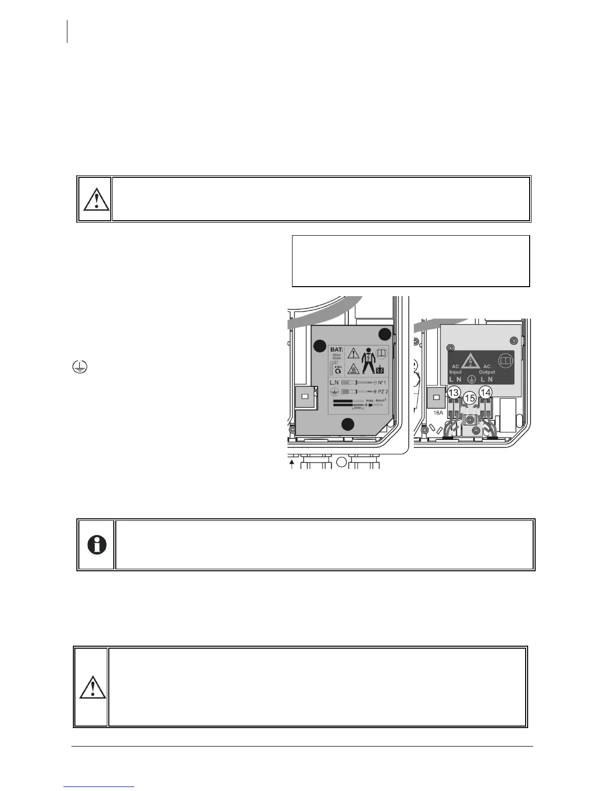
Connecting the consumers at the AC output
High voltages may be present on the connection terminals (13) and (14). Make sure that
the inverter is deactivated and that there is no AC or DC voltage present on the AC-IN
terminals and battery terminals, before proceeding with the connection.
The 230 V consumers must be connected on
the "AC-OUT" (14) connection terminals with
the wire cross-section conforming to the
standards with regard to the rated current at
the Xtender output (see fig. 1a). Distribution
must conform to the local standards and
regulations, and generally, be realised via a
distribution table.
The Xtender terminals are marked in the
following way:
N = neutral, L = live
= protective earth (connected to the
enclosure of the device).
4.5.6.1 Sizing of AC output protective
devices:
If protective devices are installed at the
output, we recommend B curve devices.
They will be sized at maximum to the highest
value listed on the unit’s nameplate at point
(37) (Fig. 1a of the Appendix) or by the
addition of the first value plus the value of the
input protective device. (i.e. inverter current
+ input current).
Cross-sections of downstream wiring must be sized accordingly
If the source assistance function (Smart Boost)(see sect. 7.2.2– p. 27 is not used; the size of the
protection device for the output (F) will be established at a maximum value equal to the rated
current of the inverter, or at the maximum value of the protection device at the input (H) if that one
exceeds the rated current of the inverter.
If the AC input (13) is not used the protective device will be sized equal or smaller than the smaller
value indicated on the nameplate on tag (37)
No downstream protective device is formally required if cross-sections of cable used for
distribution satisfy regulatory requirements for the largest rated output current listed on the
nameplate at the point (37) of Appendix 1a.
Due to the source assistance function (Smart Boost) the current at the output of the device
may be higher than the rated current of the inverter. It is the sum of the current supplied by
the additional source and the current supplied by the inverter. In this case, the dimensioning
of the output cables will be carried out by adding the current indicated on the protection
device (H) located on the upstream of the unit, to the nominal current of the inverter. (See
fig. 1a and chap. 7.2.2.4 – p. 28)
On the model XTS remove the cover plate by
unscrewing the three screws (A figure below) to
access the input/output AC terminals (13-14) and
protective earth (15).