Studer Innotec SA
Xtender
User manual V4.6.0 24
In a system comprising a single Xtender, the connection of the RCC-02 or RCC-03 units may be
conducted without stopping the Xtender (hot plug).
The communication bus will be used to interconnect other Xtender inverters in the case of a multi-
unit application or to connect other types of users who have the proprietary protocol of Studer
Innotec. In these cases, the plug-in of interconnected units is done only after the switch-off of the
installation, by disconnecting the battery or by using the main "ON/OFF" button (1) if present.
The 2 switches for the communication bus termination, "Com. Bus" (4) both remain in position
T (terminated) except when both connectors are in use. In this case, and only in this case,
both must be placed in the O open position. If one of the two connectors is not in use, the
two termination switches (14) will be in position T.
5 XTENDER PARAMETER SETTINGS
Xtender inverters have by default a number of factory settings and most of them can be modified
by the user or installer. Some basic parameters mentioned in Chapter 7 must be set at the
commissioning. For XTM and XTH models, this setting must be done by connecting the remote control
described in RCC-02/03 chap. 7.3.1 - p. 36. For the XTS model, four of them can be done directly in
the unit before powering up.
The remote control "RCC-02/-03" manual contains a complete description of available features and
associated parameters. The manual is available to download from the website www.studer-
innotec.com.
When the Xtender is connected to the remote control RCC-02/-03 or another Xtender compatible
device (VarioTrack, BSP etc.) it is possible that their software versions differ. It is important to harmonize
the software versions of all Xtender compatible products in a system. The update is made by the
remote control RCC-02/-03 from an SD card with a firmware version at least corresponding to the
most recent device.
5.1 BASIC PARAMETER SETTINGS IN THE XTS
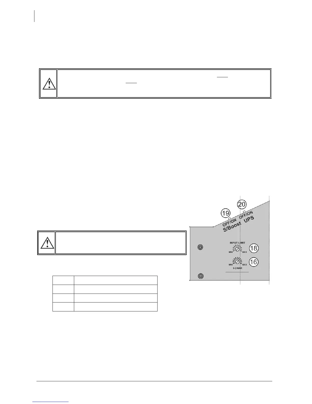
For XTS models, 4 parameters / basic functions can be modified
directly on the compartment inside the door. All other
parameters can be adjusted, if necessary, via the remote
control RCC-02/03.
• The battery current charge {1138} as described in chap.
7.3.2 - p. 30 by using the potentiometer (16)
• The max. AC source (input limit) {1107} as described in chap. 7.2.2 - p. 27 by using the
potentiometer (18). The potentiometer can be adjusted between 0 – 16 Aac.
• The source current assistance (Smart boost) function {1126} as described in chap. 7.2.2.1 - p. 27 by
using the slide button (19)
• The type of detection of AC-input loss (UPS) Fast/Tolerant/slow {1552} as described in chap. 7.2.1-
p. 27 by using the slide button (20)
These manual adjustments can be prevented using parameter {1551} on the remote control RCC-
02/-03. These values will then be defined by parameters from the remote control. If the parameter
{1551} is set to "yes" the buttons 16, 18, 19 and 20 remain inactive even if the remote control RCC-02/-
03 and/or the communication module Xcom-232i are removed after the initial setting.
 Loading...