Studer Innotec SA
Xtender
User manual V4.6.0 32
7.7 REMOTE ENTRY (REMOTE CONTROL ON/OFF)
The Xtender has one remote entry that can be assigned to a function and programmed with the
remote control RCC-02/-03 (see chapter 14.13.1 in the RCC-02/-03 user manual). By default, no
function is defined for the remote entry.
7.7.1
XTH model
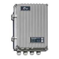
The cabling of the remote entry is done at
the terminals (7). The jumpers (6) should be
positioned correctly in function of the
desired configuration according to the
figures to the right.
Control by dry contact: the jumpers remain
in their original position, A1-2 and B2-3.
Control by a voltage (max 60V eff. / 30mA):
the jumpers are set to A1-B1 and A2-B2.
7.7.2
XTM and XTS models
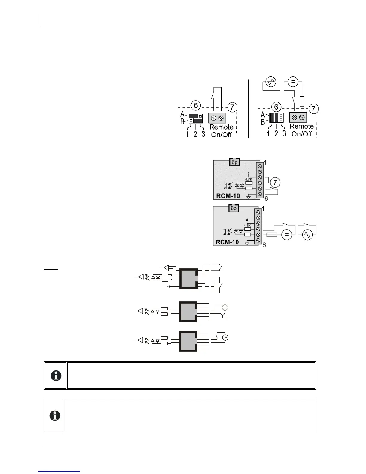
For the XTM and XTS model Xtenders, the remote entry is
available on the external (XTM) or internal (XTS) J-11/6p (15)
connector to which the external module RCM-10 is attached
(optional accessory), see chap. 9.3, p. 39.
Control by dry contact: make a bridge between terminal 3
and 4 and wire the dry contact between 5 and 6.
Control by a voltage: supply an AC or DC voltage of 6 to 60V
effective between terminals 4 and 5.
Note: on the XTM and XTS
model Xtenders, it is also
possible to achieve this control
function and on/off command
(see chap. 9.3.1) without the
RCM module. This is done by
wiring directly at the RJ11 6p
connector, as shown to the
right.
If this function is used in the mode active when contact is open (such as the emergency
stop, for example), the unused remote entries (in the other units) should be bridged
(equivalent to closed contact). The dedicated functionality will then be activated when the
drive contact opens which is connected to one of the units.