AutoProPAD Basic Key Programmer
36
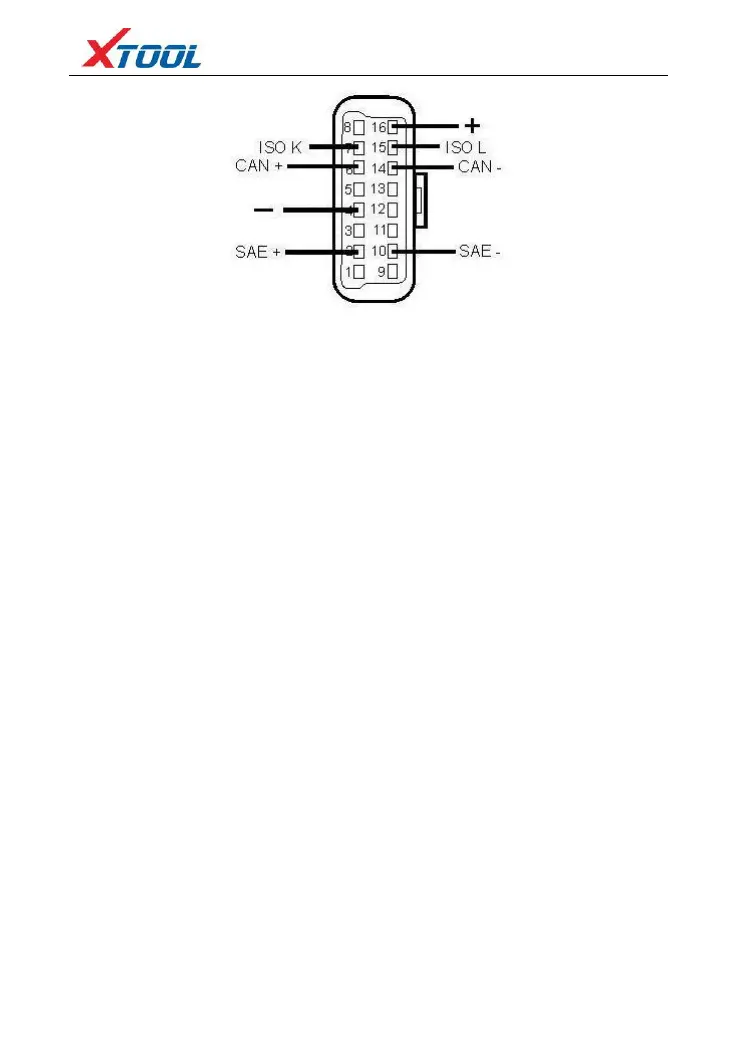
Pin Definition (Reference material)
Various pin definitions as follows:
1. Manufacturer discretion
2. SAE J1850 PWM/VPW bus positive
3. Manufacturer discretion
4. Chassis Ground
5. Signal Ground
6. ISO 15765-4 defined CAN High
7. ISO9141-2 and ISO14230-4 defined K Line
8. Manufacturer discretion
9. Manufacturer discretion
10. SAE J1850 PWM bus negative
11. Manufacturer discretion
12. Manufacturer discretion
13. Manufacturer discretion
14. ISO 15765-4 defined CAN Low
15. ISO9141-2 and ISO14230-4 defined L line
16. Battery Voltage
[1] 1, 3, 8, 9, 11, 12 and 13 are defined by manufacturer.
[2] 2, 6, 7, 10, 14 and 15 are used for diagnostic communication. Unused definitions can be
defined by manufacturers.