EasyManua.ls Logo

Xtool A80 User Manual

Xtool A80
57 pages
To Next Page IconTo Next Page
Page #1 background imageLoading...
Page #1 background image
A80 BT Intelligent Diagnosis System
1
A80 user manual
1. This manual is designed for the usage of A80, applying to A80 automotive
diagnosis platform.
No part of this manual can be reproduced, stored in a retrieval system or transmitted, in any
form or by any means (electronic, mechanical, photocopying, recording, or otherwise),
without the prior written permission of Xtool.
2. This electronic control system diagnostic unit is designed for professional vehicle
maintenance technicians. It has a certain reliability, however, it can not exclude vehicle
damage and loss caused by customer technical problems, vehicle problems or other factors, so
users need to take risks.
3. Use the device only as described in this manual. The user will be responsible solely for the
after-effects of violating the laws and regulations caused by using the product or its data
information, Xtool will not bear any legal responsibility for that.
4. Xtool shall not be liable for any incidental or consequential damages or for any economic
consequential damages arising from the accidents of individual users and the third parties,
misuse or abuse of the device, unauthorized change or repair of the device, or the failure
made by the user not to use the product according to the manual.
5. All information, specifications and illustrations in this manual are based on the latest
configurations and functions available at the time of printing. Xtool reserves the right to make
changes at any time without notice.
6. is the registered trademark of Shenzhen Xtooltech Co., Ltd.
7.In countries that the trademarks, service marks, domain names, logos and the name of the
company are not registered, Xtool claims that it still reserves the ownership of the
unregistered trademarks, service marks, domain names, logos and the company name. All
Question and Answer IconNeed help?

Do you have a question about the Xtool A80 and is the answer not in the manual?

Xtool A80 Specifications

General IconGeneral
Operating SystemAndroid
Storage16GB Internal Storage
ProcessorQuad-core
ConnectivityWi-Fi, Bluetooth
Special FunctionsInjector coding
Supported ProtocolsISO9141, KWP2000, CAN
LanguagesMultilingual support

Summary

Introduction and Disclaimers

Manual Purpose and Copyright

Manual for A80 diagnosis platform; reproduction restrictions.

User Responsibility and Liability

User risks, legal compliance, and Xtool liability limits.

Information Accuracy and Trademark

Data accuracy, update rights, and trademark notice.

Chapter I About A80 BT

1. Appearance and Layout

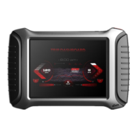
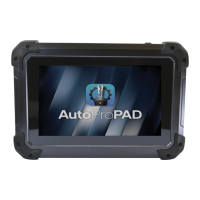
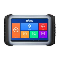
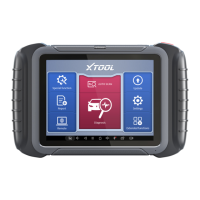
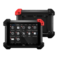
Device appearance and tablet layout details.

3. Connection and Diagnosis Steps

Connecting for diagnosis and general diagnosis steps.

Chapter III Diagnostic Link Connectors

1. Connector Locations by Model

OBD connector locations on various car models.

Chapter IV Additional Information

1. OBDII Function Description

Explanation of OBDII functionality.

Device Views

1.1 Front View

Visual representation of the device's front.

1.2 Back View

Visual representation of the device's back.

A80 BT Tablet Top and Side Views

2.1 Top View Interface and Ports

Details of top view interface and ports.

2.2 Side View Details

Details of the side view.

VCI Diagnostic Kit Outline

2.3 VCI Kit Component Descriptions

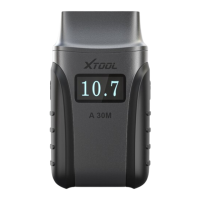
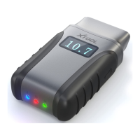
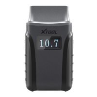
Diagram and descriptions of VCI kit components.

A80 BT Technical Parameters

System Specifications

OS, processor, memory, display, camera.

Connectivity and Power

Interfaces, battery, input voltage, working conditions.

Getting Started with A80 BT

Appearance Dimensions

Physical dimensions of the device.

Chapter II How to Use A80 BT

Introduction to usage.

1. A80 BT Activation

Process to activate the A80 BT device.

A80 BT Activation Procedure

Activation Importance and Steps

Importance of activation and step-by-step guide.

A80 BT Main Interface and Buttons

2.1 Main Interface Overview

Overview of the main user interface.

2.2 Sub-menu and Function Buttons

Description of sub-menu and buttons.

Main Interface Function Descriptions

Diagnosis Functionality

Diagnostic and special functions.

Report Functionality

Recording and saving diagnostic operations.

Additional Interface Functions

Settings Functionality

Accessing language and system settings.

XCloud and Update Functions

Cloud platform and software update.

Toolbar and Remote Assistance

Remote Assistance Feature

Accepting remote assistance from Xtool.

2.3 Toolbar Functional Buttons

Description of toolbar functional buttons.

Connection Diagnosis

3.1 Vehicle Connection Test

Steps for testing vehicle connection.

Precautions Before Use

Connection Components Overview

Main unit, VCI box, adapters.

Harness Handling and Voltage

Harness unplugging and battery voltage.

Special Function Test Requirements

Vehicle requirements for special tests.

Operational Precautions and Shutdown

Troubleshooting Data Issues

Handling incorrect test data or missing vehicles.

Device Handling and Storage

Proper device handling, shutdown, and storage.

Menu Selection for Diagnosis

4.1 Menu Navigation Guide

Guide to selecting menus for diagnosis.

Car System and Model Selection

How to navigate and select car systems/models.

Test Functions and Special Features

Special Diagnostic Functions

Overview of special diagnostic functions.

4.2 Example Test Function

Example of selecting a test function for BMW.

Common Diagnostic Menu Functions

Core Diagnostic Functions (Read/Erase Codes, Live Data)

Read Codes, Erase Codes, Live Data, Freeze Frame.

Vehicle and Component Information Functions

Vehicle Information, Component Test, Monitor Tests.

Read Version Information

Reads ECU version and system information.

Diagnostic Function Details

ECU and DTC Management

Reads and clears ECU fault codes.

Live Data Reading Explanation

Reads real-time engine parameters for diagnosis.

Component Testing and ECU Information

Actuation Component Test

Tests actuator components for proper function.

4.3 Read ECU Function

Reads ECU version information.

Reading Diagnostic Trouble Codes (DTCs)

4.4 Read DTCs Procedure

Reads fault codes stored in the ECU.

Clearing Diagnostic Trouble Codes (DTCs)

Interpreting 'No Trouble Code'

Interpreting "system normal" or "No Trouble code" messages.

4.5 Clear DTCs Process

Process for clearing fault codes.

Data Handling and Saving

Fault Code Clearing Confirmation

Confirmation message after clearing fault codes.

4.6 Read Live Data Features

Saving data as reference or recording for playback.

Special Functions and Component Tests

Diagnostic Report Review

Reviewing data playback in diagnostic reports.

4.7 Special Function Details

Details on special functions.

4.8 Actuation Component Test Conditions

Conditions for performing actuation tests.

Component Testing and Settings

Action Test Menu Navigation

Accessing action test menu for components.

5. Settings Menu

How to access and use the settings menu.

Settings: Language and Units

Language Selection

How to select the display language.

Units of Measure Selection

How to select units of measurement.

Bluetooth Setup and Connection

Unit Selection

Unit selection for measurements.

Bluetooth Pairing Steps

Steps to search for and connect Bluetooth devices.

Bluetooth and Self-Test Functions

Bluetooth Settings Configuration

Configuration of Bluetooth settings.

Self-Test for VCI Box

Performing self-test on the VCI box.

Diagnostic Report Management

6. Diagnostic Report Overview

Content and structure of diagnostic reports.

6.1 Accessing Reports

Details on accessing diagnostic reports.

Data Playback and Software Upgrade

6.2 Data Playback Feature

Feature to review recorded data streams.

7. One-Click Upgrade Process

Process for performing one-click software upgrades.

Software Updates and Cloud System

Available Software Updates

List of available software updates.

8. Xtool Cloud System Features

Benefits and features of the Xtool Cloud System.

Remote Control for Support

Seeking Remote Assistance

Seeking remote assistance from Xtool Technology Center.

Remote Control Steps

Steps for initiating and managing remote control.

TeamViewer QuickSupport Interface

Remote Support Connection Screen

Interface for remote support connection.

Diagnostic Link Connector Locations

1. Connector Locations by Model

OBD connector locations on various car models.

Diagnostic Connector Locations: Mercedes-Benz

Benz S320/220, C180, and 300SEL 140 Chassis Connectors

OBD plug locations for various Benz models.

Diagnostic Connector Locations: GM and VW

GM Buick and VW POLO Connectors

OBD plug locations for GM Buick and VW POLO.

Diagnostic Connector Locations: BMW and VW

BMW 735i and VW Passat B5 Connectors

OBD plug locations for BMW 735i and VW Passat B5.

Vehicle Diagnostic Link Connector Diagrams

Diagrams for Pick-up, Utility, and Small Cars

Diagrams for different vehicle types.

Diagnostic Link Connector Definitions

Note on Manufacturer Pin Variations

Note on variations in manufacturer pin usage.

3. Standard OBDII Diagnostic Link Connector

Definition of standard OBDII connectors.

OBDII Pin Definitions (Reference)

Pin Definitions 1-10

Details of various pin definitions (1-10).

OBDII Pin Definitions (Continued)

Pin Definitions 11-16

Details of various pin definitions (11-16).

Pin Usage Summary

Summary of pin usage for communication.

OBD II Standards and Evolution

OBD Standards and Engine Management

OBD standards and how they function in engine management.

Key OBD II Standards and Future

Key OBD II standards and the future of OBD III.

OBD III System and Sensor Functions

OBD III System Overview

Overview of the OBD III system.

1.2 Sensor Element Functionality

Function of basic sensors in car control systems.

ECU and Sensor Integration

Sensor Connection Diagram

Diagram showing sensor connections.

(1) ECU Functionality

Explanation of the Electronic Control Unit (ECU).

ECU Control and Camshaft Sensor

ECU Actuator Control and Monitoring

ECU control of actuators and monitoring.

(2) Camshaft Speed Sensor Role

Role of camshaft speed sensor in engine timing.

Camshaft and Temperature Sensors

Camshaft Speed Sensor Operation

How the camshaft speed sensor works using the Hall Effect.

(3) Temperature Sensor Usage

Various locations and uses of temperature sensors.

Temperature and Air Flow Sensors

Temperature Sensor Properties

Properties and operation of temperature sensors.

(4) Air Flow Sensor Function

Function and measurement principle of air flow sensors.

Air Flow and Intake Pressure Sensors

Air Flow Sensor Installation

Installation and operation of air flow sensors.

(5) Intake Pressure Sensor Function

Role of intake pressure sensor in fuel injection control.

Accelerator Pedal Sensor and Common Faults

(6) Accelerator Pedal Sensor Function

Function of accelerator pedal sensor in modern systems.

2. Common Faults and Elimination

Guide to troubleshooting common self-diagnosis issues.

Vehicle Self-Diagnosis Systems

Audi V6 Fault Characteristics

Fault characteristics of Audi V6 engine self-diagnosis.

Chrysler SBEC System and Fault Management

SBEC system, fault storage, and code clearing.

Volvo Self-Diagnostic System

Volvo Diagnostic Interface and Seats

Volvo diagnostic interface and seats.

Block A Diagnostic Connections

Diagnostic connections for Block A.

Volvo Diagnostic Modes and Block B

Block B Diagnostic Connections

Diagnostic connections for Block B.

Volvo Diagnostic System Modes

Volvo diagnostic capabilities and modes.

Volvo Mode Selection and Fault Clearing

Volvo Diagnostic Mode Descriptions

Diagnostic mode descriptions.

Clearing Volvo Fault Codes with Jumper

Procedure for clearing fault codes with a jumper.

Crown ABS Fault System Overview

Overview of Crown ABS fault self-diagnosis.

Crown ABS Fault Code Clearing

ABS Fault Clearing Procedure

Method to clear ABS fault codes using a jumper.

FCC Compliance Statement

FCC Compliance Conditions and Modifications

FCC compliance conditions and modification warnings.

FCC Testing and RF Exposure

FCC testing, interference measures, and RF exposure.

Related product manuals