VESDA Accessories Guide
VESDA by Xtralis
VESDAnet Terminals
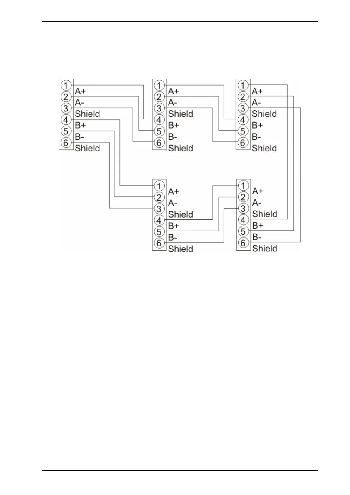
The module is connected to VESDAnet through VESDAnet terminals on the remote termination card. The
terminals enable VESDAnet communication wires to be brought into the remote box or the 19” Subrack and
looped out to another device. Data communication on VESDAnet are bidirectional. The polarity of the data
wires must be maintained throughout the network. It is recommended that RS 485 (Belden 9841 - 120 ohm)
twisted pair cables be used, however compatible cabling can be used.
Figure 3-7: An example of the wire connection for VESDAnet (Closed Loop)
Relays
The relays interface with auxiliary external items, such as loop interface modules, beacons or sounders.
These may also be interfaced with external devices through a fire indication device, or to fire alarm panels
using a High Level Interface (HLI). The relays can be programmed via a PC or the LCD programmer. The
relays can be assigned multiple assignments. Refer to software guides and LCD programmer guides for
details. Relays 3 and 6 are set for urgent fault and fire 1 respectively and can be programmed for additional
functions. For factory default settings and energized/de-energized status refer to Table 3-4 on page 13.
www.acornfiresecurity.com
www.acornfiresecurity.com