VESDA by Xtralis
VESDA Accessories Guide
Table 3-4: Relay Change State Conditions
7 Relay Card 12 Relay Card DefaultFunction
State Change
(when in factory default configuration)
1 1 Isolate Energizes when an operator isolates the detector
by pressing the Isolate key on the display module
or by activating the command via a PC or a LCD
Programmer or GPI option.
2 2 Minor Fault De-energizes when a Minor Fault is detected.
3 3 Urgent Fault De-energizes when an Urgent Fault is detected.
4 4 Alert Energizes when the Alert alarm is initiated.
5 5 Action Energizes when the Action alarm is initiated.
6 6 Fire 1 Energizes when the Fire 1 alarm is initiated.
7 7 Fire 2 Energizes when the Fire 2 alarm is initiated.
8 First Alarm Sector 1 Energizes when the First Alarm Sector 1 has been
identified.
9 First Alarm Sector 2 Energizes when the First Alarm Sector 2 has been
identified.
10 First Alarm Sector 3 Energizes when the First Alarm Sector 3 has been
identified.
11 First Alarm Sector 4 Energizes when the First Alarm Sector 4 has been
identified.
12 Scan Energizes when the Scanner is scanning the inlet
ports.
Note: Assignments to relays 3 and 6 are fixed to Urgent Fault and Fire 1 respectively.
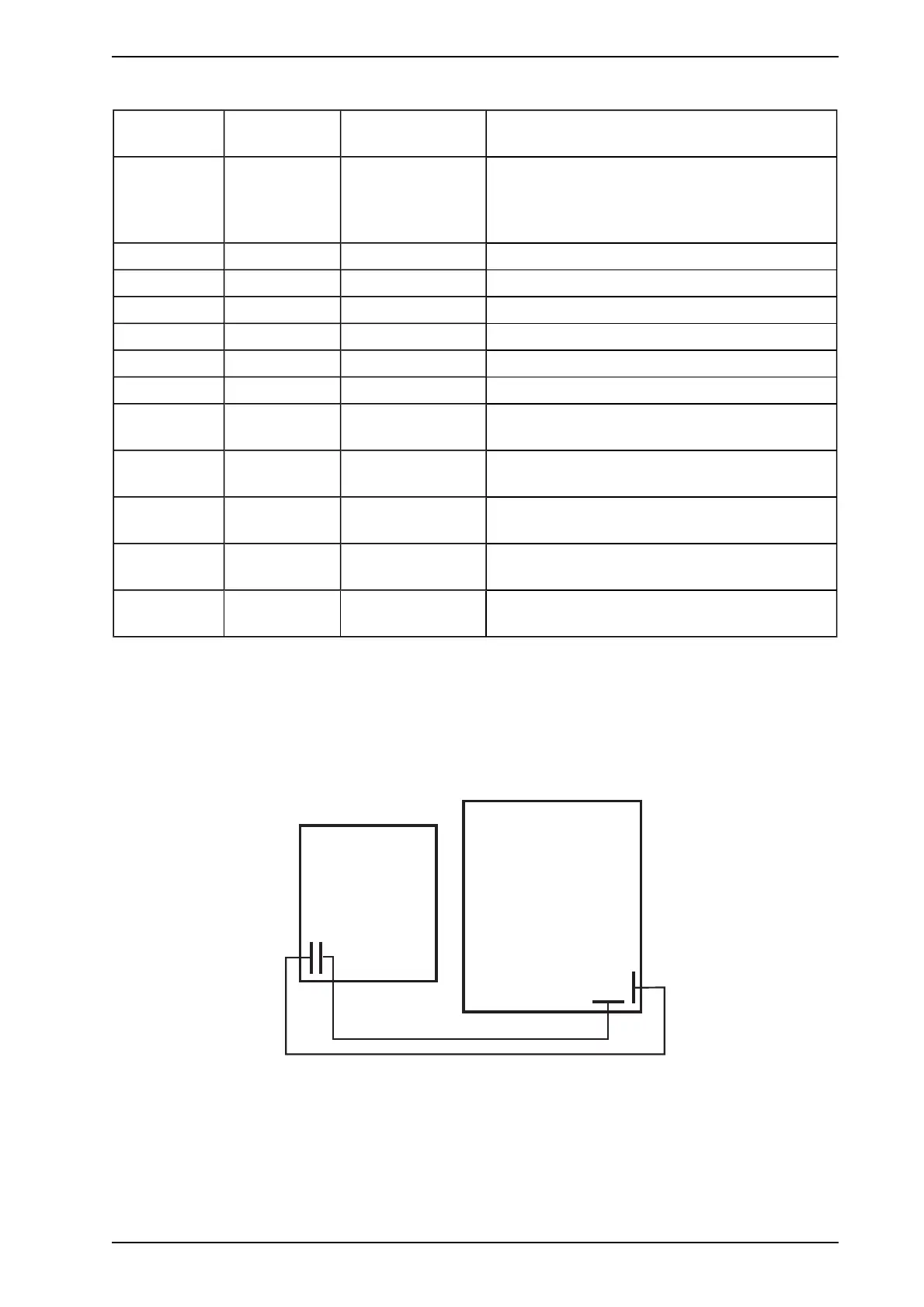
3.3.2 Wiring Relay Processor Card and Remote Termination Card
The remote termination card has a 10 way and a 11 way connector. The 10 way connector is for connecting
the relays and the 11 Way connector is for connecting the power supply and communications to the relay
processor card.
RelayProcessorCard
Remote TerminationCard
11way(PowerandCommunications)
11way
Connector
10way
Connector
10way(Relays)
10way
Connector
11way
Connector
Figure 3-8: Internal wiring between Module Processor Card and Remote Termination Card
3.3.3 Wiring the Modules in the 19” Subrack
The VESDAnet and power connections are looped internally from the factory. It is only necessary to connect
power on to the rack and VESDAnet in and out of each end of the rack.
www.acornfiresecurity.com
www.acornfiresecurity.com