
P
Patricia ThomasSep 3, 2025
What does a red status light mean on my Xylem Water Pump?
- BBryce SmithSep 3, 2025
A red status light on your Xylem Water Pump indicates a pump failure. Check the displayed error code and find the cause from table 8.3.
What does a red status light mean on my Xylem Water Pump?
A red status light on your Xylem Water Pump indicates a pump failure. Check the displayed error code and find the cause from table 8.3.
Why is my Xylem ecocirc XL so noisy?
A noisy Xylem Water Pump can be caused by several factors: 1. It might not be thoroughly vented. Try switching off the pump and, after 30 seconds, switching it back on to restart the automatic air-venting procedure. 2. Cavitation could be occurring due to insufficient suction pressure. Increase the system suction pressure within the admissible range. 3. There might be foreign objects in the pump. Clean the system to remove any debris. 4. The bearing might be worn out, and in this case, you should replace the pump.
What should I do for alarm code A01 on my Xylem ecocirc XL Water Pump?
If your Xylem Water Pump displays alarm code A01, which indicates a fluid sensor malfunction, switch off the pump for 5 minutes and then power it back on. If the problem persists, contact local B&G representative.
What to do if my Xylem ecocirc XL shows error E09?
If your Xylem Water Pump displays error code E09 and doesn't start, it indicates a hardware error. Restart the pump.
What should I do if my Xylem Water Pump shows error E05?
If your Xylem Water Pump displays error code E05 and does not start, it indicates that the data memory is corrupted. Try restarting the pump.
Why my Xylem ecocirc XL doesn't start and shows error E02?
If your Xylem Water Pump displays error E02 and doesn't start, it means there's high motor current. Try restarting the pump.
What should I do if my Xylem ecocirc XL Water Pump doesn't start (E01)?
If your Xylem Water Pump is showing error code E01 and won't start, it indicates that internal communication has been lost. Restart the pump.
How do I fix a Xylem Water Pump that won't start (E11)?
If your Xylem Water Pump is not starting and shows error code E11, it indicates a loss of phase. Check the power supply to ensure all phases are present and correctly connected.
Why won't my Xylem ecocirc XL Water Pump start and shows error E07?
Error code E07 on your Xylem Water Pump indicates a motor thermal protection trip. Check for any foreign material around the impeller and rotor that could cause an overload. Also, check the installation conditions and the temperature of the water and ambient air. Allow the motor to cool down, and then try restarting the pump.
What to do if the circuit breaker trips on my Xylem Water Pump?
If the circuit breaker trips for your Xylem Water Pump, reset the power supply circuit breaker. Then, determine the cause for the overload that tripped the breaker.
Explains hazard levels, symbols, and categories for safe operation.
Guidelines for emissions and waste disposal according to local regulations.
Warning about using only original spare parts for replacements.
Steps to inspect the package and product for damage or missing items.
Instructions for positioning, fastening, and precautions during transport.
Recommendations for storage location, temperature, and humidity.
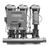
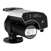
Describes the ecocirc XL as a wet rotor pump with energy-efficient motor.
Explains the naming convention for ecocirc XL pump models.
Lists detailed specifications like voltage, frequency, IP protection, and temperature ranges.
Provides sound pressure levels for different nominal pump HP.
Lists items included in the package with the pump unit.
Lists optional accessories available for the ecocirc XL pumps.
Safety warnings and guidelines for lifting and handling the pump.
Lists necessary tools for installing the pump.
Guidelines and warnings for selecting a suitable pump installation location.
Table detailing required inlet pressure based on fluid temperature.
Table showing power draw decrease based on temperature.
Precautions and checklist for correct piping installation.
Checklist for electrical supply, grounding, and wire specifications.
General steps for installing the pump, including orientation and insulation.
Detailed steps for rotating the motor housing for better access.
Precautions and steps for electrical connections, including grounding.
Instructions for connecting the power supply to the pump's terminal box.
Steps for connecting input/output wires to the terminal blocks.
Guidelines for wiring, cable types, and specific connections for pumps.
Overview of the pump's user interface, buttons, and display elements.
How to lock and unlock the user interface for safety and convenience.
Introduces main pump functions and control modes selectable via interface or I/O.
Details on Constant pressure, Proportional pressure, and Fixed speed modes.
Explains modes like Δp-T, T-Constant, and ΔT constant.
Description of the energy-saving night mode function.
How to start or stop the pump using external dry contacts or relays.
Using a 0-10 V analog input to control pump speed or mode.
Information about dry relay contacts for status indication.
Specifics of signal relays for three-phase pump status.
Setup for optional differential pressure and temperature sensors.
Details on RS-485 communication for BMS integration.
Information on the optional wireless module for control.
Configuration for backup, alternate, and automatic parallel operation.
Methods to configure pump settings via UI, bus, or wireless.
Steps to adjust baud rate, protocol, address, and module type.
How to change the pump's operating mode using the user interface.
Procedure to adjust the desired set point for pump operation.
How to switch between different units for displayed parameters.
Methods for starting and stopping the pump manually or via command.
Explains the automatic air venting process and how to recall/skip it.
Steps to configure two pumps for parallel operation.
How to set backup, alternate, or parallel modes for two pumps.
Explains how alarms and errors are displayed on the interface.
Recommends periodic inspections to check for potential pump problems.
Lists display messages for normal operation and status lights.
Details fault codes, their causes, and solutions for Red LED indicators.
Lists alarm codes, their causes, and solutions for Orange LED indicators.
Specific faults like "pump does not start" and their remedies.
Information on the license agreement for embedded software.
| Insulation Class | F |
|---|---|
| Frequency | 50/60 Hz |
| Power Supply | 230 V, 50/60 Hz |
| Motor Type | ECM |
| Motor Protection | IP42 |
| Control Modes | Constant speed |
| Connections | Flange |