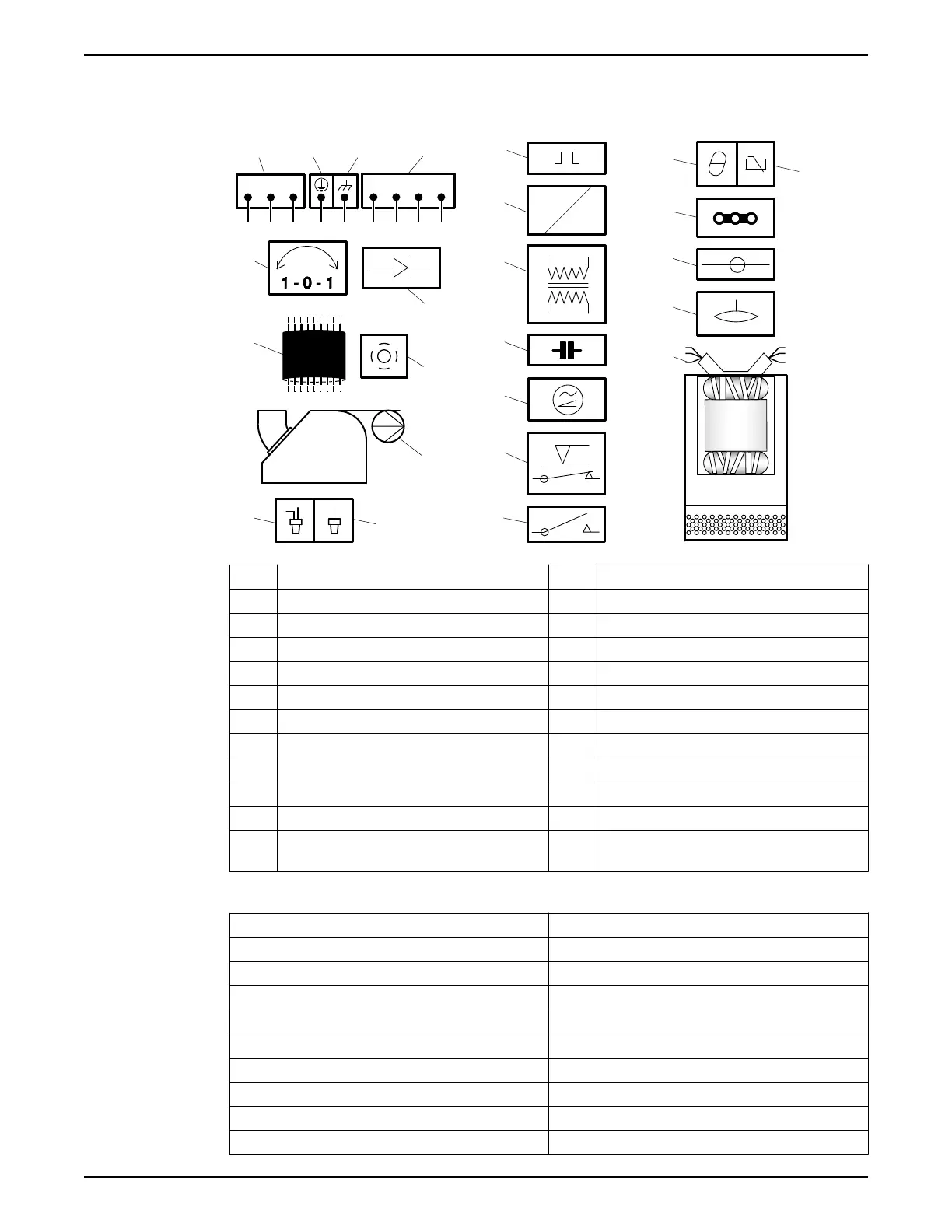
4.2.2 Cable charts
Connection locations
WS001021B
L1 L2 L3
T3 T4T1 T2
15
13
14
42 31
7
10
5
9
8
6
11
12
17
16
24
22
23
19
20
21
18
1 Starter equipment and main leads (L1, L2, L3) 13 Coil
2 Ground (earth) 14 Transformer
3 Functional ground 15 Capacitor
4 Control leads (T1, T2, T3, T4) 16 Softstarter
5 Phase shifter 17 Level regulator
6 Diode 18 Contactor, start relay or thermal relay
7 Motor cable 19 Thermal detector in stator
8 Screen 20 Thermal detector in main bearing
9 Pump 21 Jumper
10 Crimp connection 22 Terminal board, terminal plate
11 Crimp isolation 23 Leakage sensor
12 Motor protector 24 Stator leads (U1, U2, U5, U6, V1, V2, V5, V6, W1,
W2, W5, W6, Z1, Z5, Z6)
Color code standard
Code Description
BN Brown
BK Black
WH White
OG Orange
GN Green
GNYE Green-Yellow
RD Red
GY Grey
BU Blue
4 Installation
16 2008 Ready 8, 8S Installation, Operation, and Maintenance
 Loading...