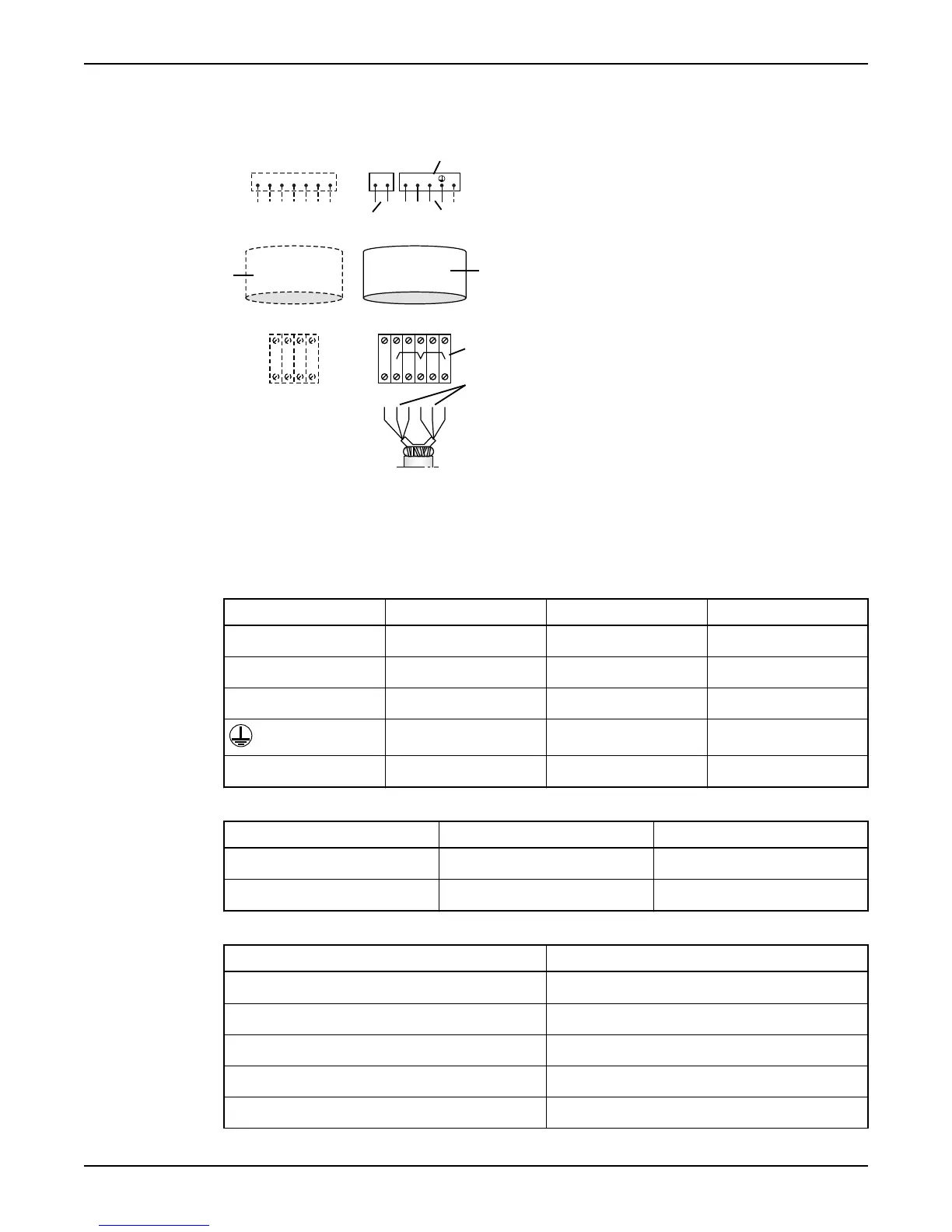
Cable charts
Connection locations
1 2 3 4 5 6 7
1 2 L1 L2 L3 GC
U1 W2 V1 U2T16 T15 T2 T1 W1 V2
1
2
3
6
5
4
7
1. Control leads
2. Starter equipment
3. Mains leads
4. Motor cable
5. Terminal blocks on pump
6. Stator leads
7. Control cable
Colors and marking of the mains leads
Mains SUBCAB 7GX SUBCAB 4GX SUBCAB AWG
L1 Black 1 Brown Red
L2 Black 2 Black Black
L3 Black 3 Grey White
Yellow/Green Yellow/Green Yellow/Green
Groundcheck (GC) - - Yellow
Color and marking of the control leads
Control SUBCAB 7GX and SUBCAB 4GX SUBCAB AWG
T1 White T1 Orange
T2 White T2 Blue
Colors of the stator leads
Stator connection Lead color
U1 Red
U2 Green
U5 Red
V1 Brown
V2 Blue
Installation
24 Flygt 3201 Installation, Operation, and Maintenance Manual