10
A.O. SMITH / CENTURY MOTOR TERMINAL
BOARD AND VOLTAGE CHANGE PLUG
■ Pumps are Pre-Wired by HP:
• ½ hp wired for 115 volts
• ¾ hp - 1½ hp and larger wired
for 230 volts
• 2 hp is 230 volt only
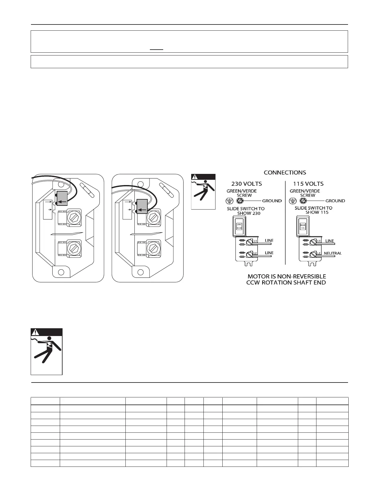
NIDEC MOTOR
• Slide voltage switch to desired voltage prior to wir-
ing.
WARNING: DISCONNECT POWER SOURCE BEFORE CHECKING. DO NOT MAKE
ANY CHANGES WITH POWER ON.
TECHNICAL DATA
TECHNICAL DATA
VOLTAGE CHANGES ARE MADE INSIDE THE MOTOR COVER, NOT IN THE PRESSURE SWITCH.
Fig. 7
DANGER
Hazardous voltage
can shock, burn or
cause death.
A.O. SMITH / CENTURY MOTOR DATA
GWT Number Where Used A.O. Smith Number HP Volts Phase Service Factor Max. Load Amps Watts Circuit Breaker
J04853L J5(S), GB C48A93A06 ½ 115/230 1 1.6 10.8/5.4 968 25/15
J05853L J7(S), GB, GT07, (H)SJ07, HSC07 C48A94A06 ¾ 115/230 1 1.5 14.8/7.4 1336 30/15
J06853L J10(S), GB, GT10, (H)SJ10, HSC10 C48A95A06 1 115/230 1 1.4 16.2/8.1 1592 30/20
J07858L J15(S), GB, GT15, HSJ15, HSC15 C48C53A06 1½ 115/230 1 1.3 21.4/10.7 1950 40/20
➀ J08854L HSJ20, GB, GT20, HSC20 K48A34A06 2 230 1 1.4 12.9 2100 25
J09853 XSH30, GT30 7-196427-20 3 230 1 1.15 13.3 3280 30
SFJ04860 JRS5, JRD5, JB05 C48C04A06 ½ 115/230 1 1.6 12.6/6.3 990 25/15
SFJ05860 JRS7, JRD7, JB07 C48C05A06 ¾ 115/230 1 1.5 14.8/7.4 1200 30/15
SFJ06860 JRS10, JRD10, JB10 C48C06A06 1 115/230 1 1.4 16.2/8.1 1400 30/20
➀ Effective July, 1998, 230 V only.
VOLTAGE CHANGE PROCEDURE AND TERMINAL BOARD DESIGN
Jet pump motors have a voltage plug to facilitate simple voltage changes from 115V to 230V. All ½ HP motors
are factory wired for 115V operation. If wired for 115V, operation at 230V will destroy the windings in a matter of
seconds and will not be covered by warranty. Larger HP motors are factory wired at 230V.
A.O. Smith / Century Terminal Board Design:
• L1 has two (2) male terminals, one switch wire is attached to one terminal.
• L2 has two (2) male terminals, one switch wire is attached to one terminal and when set up for 115V operation the
voltage plug is connected to the other.
• “A” has 1 male terminal, the voltage plug is always connected to “A”.
A.O. Smith / Century Voltage Change: failure to follow these instructions may damage the windings
• 115V - Place the Black voltage plug on the open L2 male terminal and the “A” terminal.
• 230V - Place the Black voltage plug only on the “A” male terminal. The 2nd L2 male terminal will be open.
L1
L2
A
115V
230V
L1
L2
A
115V
230V
DANGER
Hazardous voltage
can shock, burn or
cause death.
 Loading...