45
Connection example:
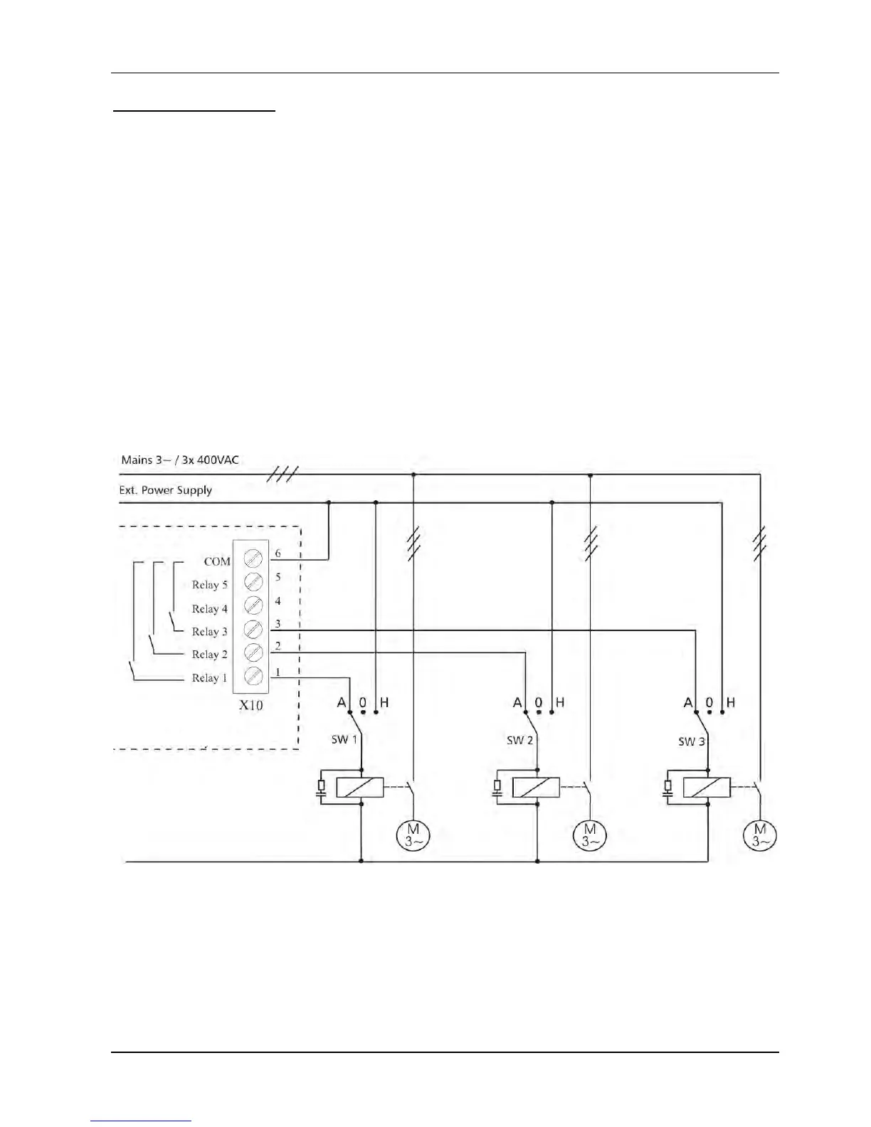
The following wiring diagram shows a standard cascade control system where the
HYDROVAR is fitted with an additional Relay Card, in selected mode Cascade Relay.
To switch the fixed speed pumps via the internal Relay Card, an external panel for the
contactors of the D.O.L or STAR/DELTA starters (and optional A/0/M – switch) is required.
In the example below 3 fixed speed pumps are connected to the Relay Card. For such an
application, an optional HAND/OFF/AUTO switch (SW1, SW2, and SW3) is recommended.
- During normal operation the switch is set to AUTO, so the Relay Card of the HYDROVAR
starts and stops the connected pumps.
- The HAND position allows a manual operation of the pumps.
- If one of the additional switches is in OFF position, the related relay must be disabled in
the submenu STATUS [20] to ensure correct operation of the multi-pump system.
HYDROVAR Relay Card

 Loading...

