Do you have a question about the Yaesu FT-180A and is the answer not in the manual?
Covers frequency, emission type, channels, operating temperature, power requirements, case size, and weight.
Details power output, unwanted sideband suppression, carrier suppression, spurious emissions, and distortion products.
Details receiver sensitivity, selectivity, type, IF, rejection, and audio output specifications.
Lists various integrated circuits used in the device, with part numbers.
Lists various field-effect transistors used in the device.
Lists standard transistors used in the device.
Lists various diodes used in the device.
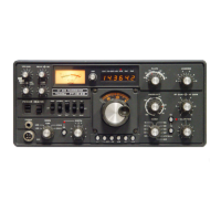
Describes the eight-pin microphone input jack and its impedance.
Details the headphone jack, its impedance, and function.
Explains the main power switch and its function for transceiver and accessories.
Describes the function of the noise blanker switch.
Details the momentary switch for tone calling and calibration.
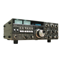
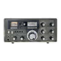
Explains how the meter switch selects display functions for receive and transmit.
Describes the switch for selecting operating modes (LSB, USB, AM).
Details the manual gain control for RF and IF stages.
Explains the control for setting the audio output (volume) level.
Describes the squelch control for quieting the receiver.
Explains the control for fine-tuning received signals.
Details the switch for selecting the operating channel.
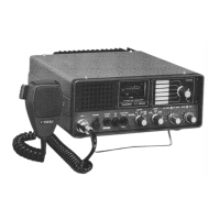
Describes the front panel S-meter, FWD/REF PO meter, IC meter and source voltage meter.
Identifies the grill for the internal speaker.
Details the external speaker output jack and its function.
Explains the importance of a good ground connection.
Describes the SO-239 antenna jack.
Details how to connect the DC power cord.
Explains the 20-pin connector for the optional remote controller.
Details the 12-pin connector for the optional antenna coupler.
Discusses antenna importance, impedance requirements, and types.
Details the installation of a doublet or dipole antenna, including formulas.
Explains the installation of a quarter wave antenna and its length calculation.
Details the requirements for a good earth ground connection.
Details DC supply capacity, voltage, and fuse requirements.
Explains AC power voltage, fuse requirements, and connection.
Warns about permanent damage from reversed polarity supply voltage.
Recommends installing away from Electronic Fuel Injection carburetor components.
Explains the use of the 1500 Hz tone generator for selective calling.
Warns against changing channels or modes while transmitting to prevent damage.
Details power requirements, functions, AF output, microphone, dimensions, and weight.
Provides instructions for positioning and mounting the FH-180.
Explains setting power, channels, volume, and transmitting with the controller.
Notes that the handset must be pressed snugly into the cradle when not in use.
Explains the RF input, amplification, mixing, and IF stages of the receiver.
Clarifies part number differences for units with and without crystal ovens.
Explains the audio input, modulator, IF stages, and RF amplification for transmission.
Details the SSB signal path from audio input to RF output.
Explains the AM signal path, including carrier injection.
Details the pre-driver, drivers, and final amplifiers for power output.
Explains part number conventions for 50W (8XXX) and 100W (9XXX) models.
Details the driver and final amplifiers for the 10W version.
Explains the ALC circuit for overdrive and high SWR protection.
Lists RF signal generators, voltmeters, dummy loads, and oscilloscopes needed.
Lists AF signal generators, receivers, frequency counters, and oscilloscopes.
Details receiver alignment procedures.
Details aligning antenna and RF coils for maximum S-meter deflection.
Notes that all channels are simplex, for duplex see page 41.
Details aligning RX mixer coils for maximum S-meter deflection.
Describes aligning RX trap coils for minimum audio voltmeter and S-meter indication.
Details adjusting IF coils for maximum S-meter reading.
Details adjusting NB coils for minimum deflection on a DC voltmeter.
Describes the procedure for aligning the S-meter deflection.
Details adjusting the product detector for minimum S-meter reading.
Details aligning balanced modulator coils for maximum VTVM reading.
Describes adjusting for minimum signal indication on an external receiver.
Details aligning TX mixer coils for maximum VTVM reading.
Details aligning TX IF trap coils using a spectrum analyzer for minimum spurious levels.
Details aligning TX IF coils for maximum VTVM deflection.
Describes aligning the IC meter and setting idling current.
Details adjusting the FWD meter to 80% of full scale.
Details the procedure for aligning the ALC circuit for optimal power output.
Continues the ALC alignment procedure, including power output adjustments.
Warns against adjusting specific VRs without the full ALC procedure to avoid damage.
Details aligning the carrier/local oscillator frequency and phase.
Clarifies part number differences for units with and without crystal ovens.
Describes aligning the tone oscillator for the correct frequency and output voltage.
Provides step-by-step instructions for installing an LSB filter.
Details the procedure for installing an optional crystal oven.
Clarifies crystal specifications for units with and without ovens.
Details installing crystals and transformers for simplex channels.
Continues installation steps for simplex channels, including jumper wires.
Details installing crystals, transformers, and capacitors for semi-duplex channels.
Provides step-by-step instructions for modifying the FT-180A for FH-180 controller use.
Lists components for the main chassis, including transistors, resistors, capacitors.
Lists components for the RF unit, including FETs and transistors.
Continues listing components for the RF unit, including resistors and capacitors.
Notes limitations for specific channel frequency ranges.
Lists components for the IF unit, including ICs, FETs, transistors, diodes, filters.
Lists components for the AF unit, including ICs, transistors, potentiometers, capacitors.
Continues listing AF unit components like transistors, capacitors, and inductors.
Lists components for the 10W and 50W Power Amplifier units.
Continues listing 50W PA unit components, including transistors, diodes, resistors, capacitors.
Continues listing 10W PA unit components, including transistors, diodes, resistors, inductors.
Lists general electronic components like potentiometers and capacitors.
Lists components for the crystal oven, chassis, and control unit.
Lists various general electronic components by type.
Lists components for the heater unit.
Lists inductor and transformer components.
Lists components for the Carrier/Local Oscillator Unit.
Lists various miscellaneous components by type.
Lists transistor, diode, and resistor components.
Lists components for the 100W Power Amplifier unit.
Lists components for the 50W Power Amplifier unit.
Lists components for the connector unit, including connectors and cables.
Lists components for the FH-180 modification kit.
| Brand | Yaesu |
|---|---|
| Model | FT-180A |
| Category | Transceiver |
| Language | English |