Yale Electric Chain Hoist CPE
electric
Yale
11
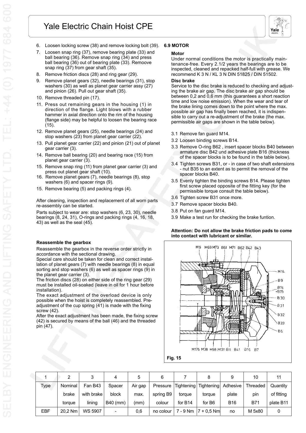
Fig. 15
6. Loosen locking screw (38) and remove locking bolt (39).
7. Loosen snap ring (37), remove bearing plate (33) and
ball bearing (36). Remove snap ring (34) and press
ball bearing (36) out of bearing plate (33). Remoove
snap ring (37) from gear shaft (35).
8. Remove friction discs (28) and ring gear (29).
9. Remove planet gears (32), needle bearings (31), stop
washers (30) as well as planet gear carrier assy (27)
and pinion (26). Pull out gear shaft (35).
10. Remove threaded pin (17).
11. Press out remaining gears in the housing (1) in
direction of the flange. Light blows with a rubber
hammer in axial direction onto the rim of the housing
(flange side) may be helpful to loosen the bearing race
(15).
12. Remove planet gears (25), needle bearings (24) and
stop washers (23) from planet gear carrier (22).
13. Pull planet gear carrier (22) and pinion (21) out of planet
gear carrier (3).
14. Remove ball bearing (20) and bearing race (15) from
planet gear carrier (3).
15. Remove snap ring (11) from planet gear carrier (3) and
press out planet gear shaft (10).
16. Remove planet gears (7), needle bearings (8), stop
washers (6) and spacer rings (9).
15. Remove bearing (5) and packing rings (4).
After cleaning, inspection and replacement of all worn parts
re-assembly can be started.
Parts subject to wear are: stop washers (6, 23, 30), needle
bearings (8, 24, 31), O-rings and packing rings (4, 16, 18,
43) as well as the seal (45).
Reassemble the gearbox
Reassemble the gearbox in the reverse order strictly in
accordance with the sectional drawing.
Special care should be taken for clean and correct instal-
lation of planet gears (7) with needle bearings (8) in equal
sorting and stop washers (6) as well as spacer rings (9) in
the planet gear carrier (3).
The friction discs (28) on either side of the ring gear (29)
must be installed oil-soaked (leave in oil for 1 hour before
installation).
The exact adjustment of the overload device is only
possible when the hoist is completely reassembled. Pre-
adjustment of the cup spring (41) is made with the fixing
screw (42).
After the exact adjustment has been made, the fixing screw
(42) is secured by means of the ball (46) and the threaded
pin (47).
6.9 MOTOR
Motor
Under normal conditions the motor is practically main-
tenance-free. Every 2.1/2 years the bearings are to be
inspected, cleaned and repacked half-full with grease. We
recommend K 3 N / KL 3 N DIN 51825 / DIN 51502.
Disc brake
Service to the disc brake is reduced to checking and adjust-
ing the brake air gap. The disc brake air gap should be
between 0,2 and 0,6 mm (this guarantees a short reaction
time and low noise emission). When the wear and tear of
the brake lining comes down to the point where the max.
possible air gap has finally been reached, it is indispen-
sible to carry out a re-adjustment of the brake (the max.
permissible air gaps are shown in the table below).
3.1 Remove fan guard M14.
3.2 Loosen binding screws B14.
3.3 Remove O-ring B62 , insert spacer blocks B40 between
armature disc B42 und adhesive plate B16 (thickness
of the spacer blocks is to be found in the table below).
3.4 Tighten screws B31, or - in case of two shaft extensions
- nut B35 to an extent as to permit the removal of the
spacer blocks B40.
3.5 Evenly tighten the binding screws B14. Please tighten
first screw placed opposite of the fitting key (for the
permissible torque consult the table below).
3.6 Tighten screw B31 once more.
3.7 Remove spacer blocks B40.
3.8 Put on fan guard M14.
3.9 Make a test run for checking the brake funtion.
Attention: Do not allow the brake friction pads to come
into contact with lubricant or similar.
1234567891011
Type Nominal Fan B43 Spacer Air gap Pressure Tightening Tightening Adhesive Threaded Quantity
brake with brake block max. spring B9 torque torque plate pin of fitting
torque lining B40 (mm) (mm) colour for B14 for B6 B16 B71 plate B11
EBF 20,2 Nm WS 5907 - 0,6 no colour 7 - 9 Nm 7 + 0,5 Nm no M 5x80 0
 Loading...