Yale Electric Chain Hoist CPE
electric
Yale
5
B
b
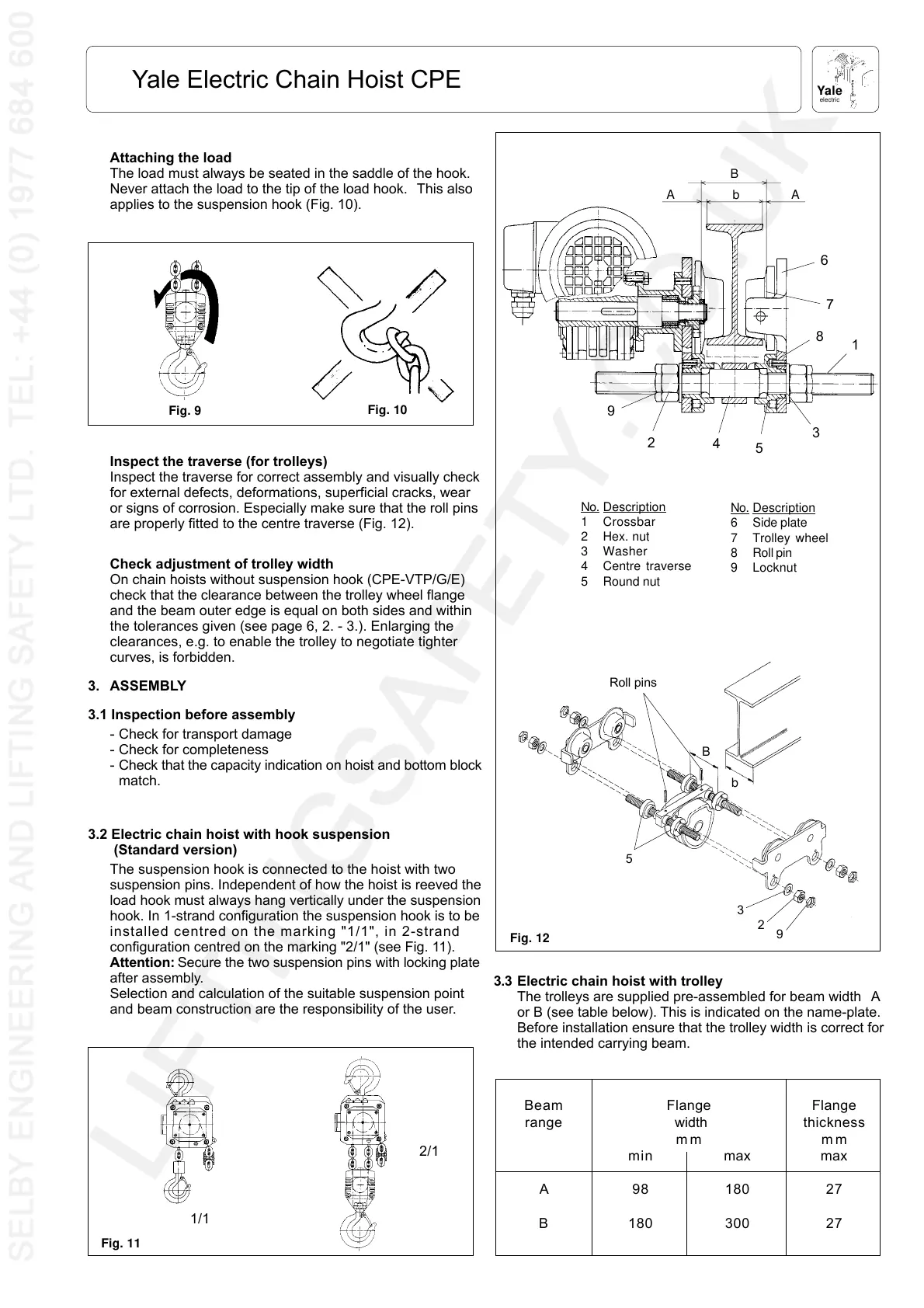
No. Description
1Crossbar
2 Hex. nut
3 Washer
4Centre traverse
5 Round nut
No. Description
6Side plate
7Trolley wheel
8Roll pin
9 Locknut
Roll pins
bA
A
B
Electric chain hoist with trolley
The trolleys are supplied pre-assembled for beam width A
or B (see table below). This is indicated on the name-plate.
Before installation ensure that the trolley width is correct for
the intended carrying beam.
Attaching the load
The load must always be seated in the saddle of the hook.
Never attach the load to the tip of the load hook. This also
applies to the suspension hook (Fig. 10).
Inspect the traverse (for trolleys)
Inspect the traverse for correct assembly and visually check
for external defects, deformations, superficial cracks, wear
or signs of corrosion. Especially make sure that the roll pins
are properly fitted to the centre traverse (Fig. 12).
Check adjustment of trolley width
On chain hoists without suspension hook (CPE-VTP/G/E)
check that the clearance between the trolley wheel flange
and the beam outer edge is equal on both sides and within
the tolerances given (see page 6, 2. - 3.). Enlarging the
clearances, e.g. to enable the trolley to negotiate tighter
curves, is forbidden.
3. ASSEMBLY
3.1 Inspection before assembly
- Check for transport damage
- Check for completeness
- Check that the capacity indication on hoist and bottom block
match.
3.2 Electric chain hoist with hook suspension
(Standard version)
The suspension hook is connected to the hoist with two
suspension pins. Independent of how the hoist is reeved the
load hook must always hang vertically under the suspension
hook. In 1-strand configuration the suspension hook is to be
installed centred on the marking "1/1", in 2-strand
configuration centred on the marking "2/1" (see Fig. 11).
Attention: Secure the two suspension pins with locking plate
after assembly.
Selection and calculation of the suitable suspension point
and beam construction are the responsibility of the user.
Fig. 12
1
2
3
4
5
6
7
8
9
5
3
2
9
Fig. 10
Fig. 9
2/1
1/1
Fig. 11
3.3
Beam Flange Flange
range width thickness
mm mm
min max max
A98180 27
B 180 300 27
 Loading...