11
CD-C600
CD-C600
Fig. 3
Fig. 6
Fig. 7
Fig. 4
Fig. 5
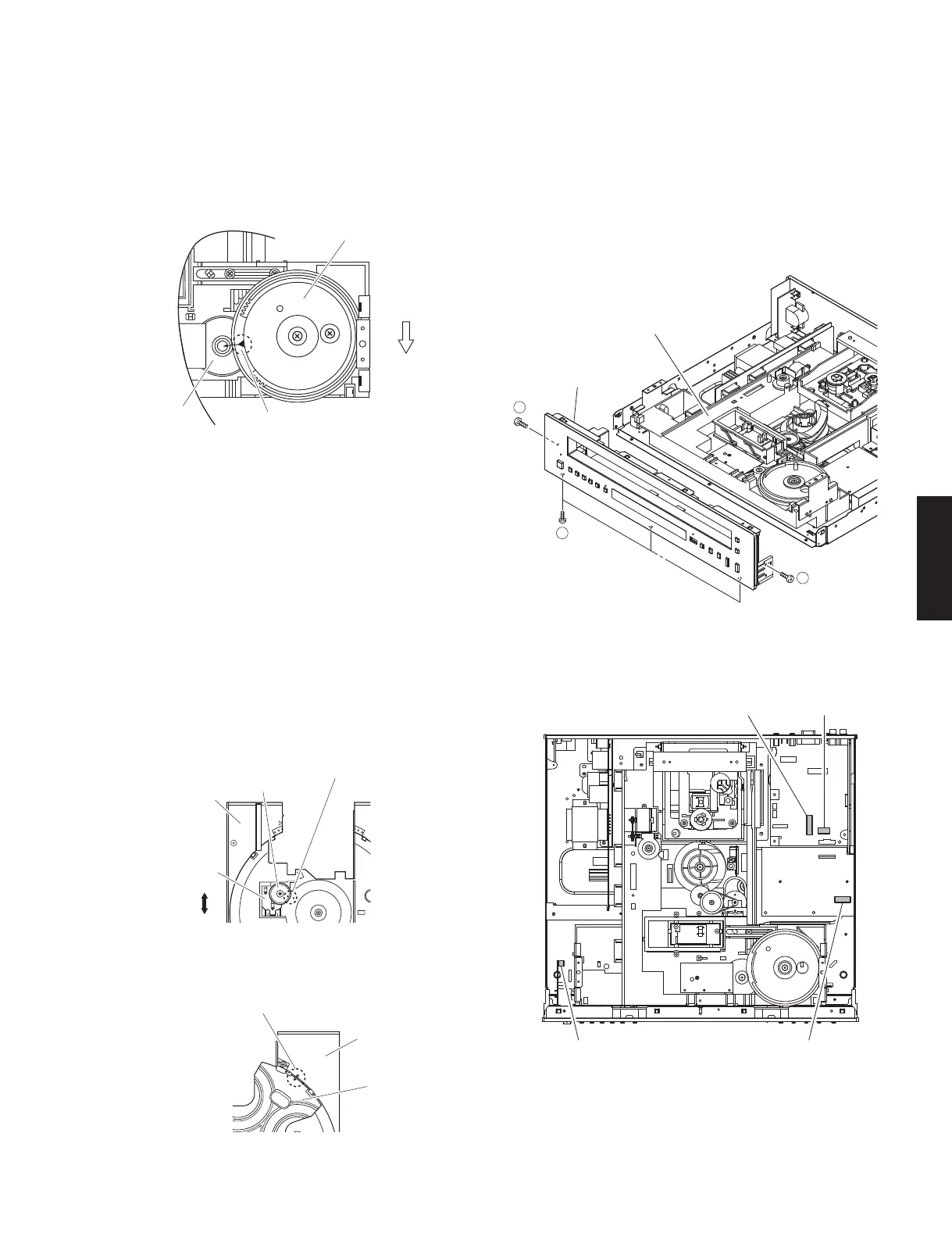
• Precaution for installation of the Disc Tray Ass’y.
On disc tray ass’y setting.
Check the direction of marking “
▲
” on gear according
to this drawing. (Fig. 3)
CM-230B unit can not be removed without
removing the Front Panel Unit.
5-A. Removal of Front Panel Unit
a. Remove 2 screws (
⑦
) and 3 screws (
⑧
). (Fig. 6)
b. Remove CB6, CB304, CB804 and CB809. (Fig. 7)
c. Remove the front panel unit. (Fig. 6)
• IMPORTANCE: Installation of Table.
Install the table according to the following procedure.
a. Slide the lever so that the gear/RT1 becomes
free. (Fig. 4)
b. With the “
▲
” mark on the gear/RT1 aligned with
the same mark on the disc tray, lock it with the
lever. (Fig. 4)
c. Install the table by aligning it to the thick line on “ / ”
mark. (Fig. 5)
* Check that the table is locked after installation.
Front panel
Gear/L0
Marking
Gear/L01
Fit the gear/RT1 to "▲" mark.
Gear/RT1
Lever
Lock
Unlock
Disc tray ass'y
Disc tray
Table
Fit the table to the thick line on " / " mark.
CM-230B unit
Front panel unit
7
7
8
CB809
CB304 CB6
CB804