27
CD-C600
CD-C600
Pin
No.
Function
Name
I/O State During a Reset Detail of Function
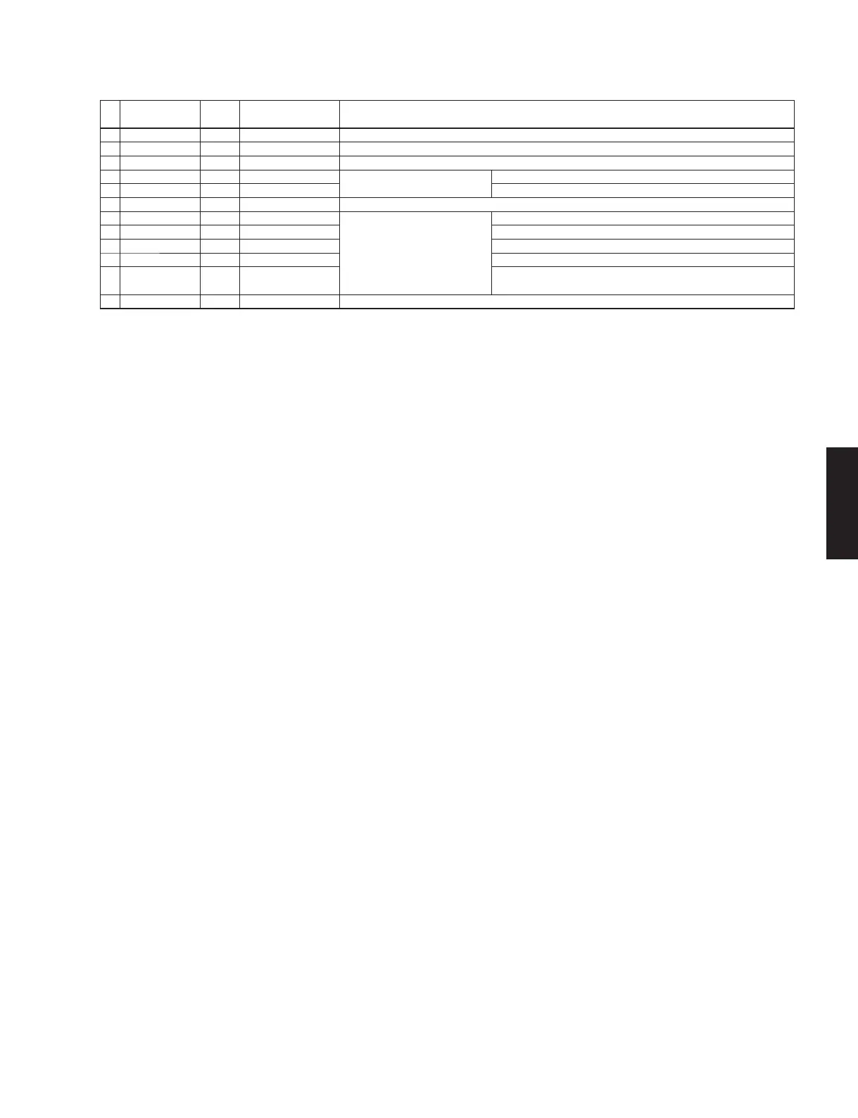
69 DOUT O Low Monitor pin / Digital audio data output (EIAJ format)
70 CONT4 I/O Input (Low) General purpose input/output 4 (Initial : Input, internal pull-down resistor ON)
71 XVSS — — Oscillator ground / This pin must be connected to the 0 V level
72 XOUT O Oscillation
Oscillation
16.9344 MHz oscillation pins
73 XIN I Oscillation 16.9344 MHz oscillation pins
74 XVDD — — Oscillator power supply
75 LRVDD — —
D/A Converter
Left/Right channel power supply
76 LCHO AO LRVDD/2 Left channel output
77 LRREF AO LRVDD/2 Reference output for Left/Right channel
78 RCHO AO LRVDD/2 Right channel output
79 LRVSS — —
Left/Right channel ground
This pin must be connected to the 0 V level
80 SLCO AO Undefined Slice level control output
Note
①
For the unused pins:
• The unused input pins must be connected to the GND (0 V) level
• The unused output pins must be leave open (No connection)
• The unused input/output pins must be connected to the GND (0 V) or power supply pin for I/O in input pin mode or must be left open (No connection) in
output pin mode
②
NC pins must be left open
③
For power supply pins:
• Same voltage must be supplied to DVDD, AVDD, XVDD, LRVDD, VVDD1, VVDD3 power supply pins (Refer to allowable operating ranges)
④
MODE pin must be connected to the DVDD
⑤
TEST pins must be connected to GND (0 V)
⑥
During power-on, RESB pin must be set to “Low” for more than 20 ms
⑦
Nch-opendrain output pin must put the pull-up resistance outside