29
CD-C600
CD-C600
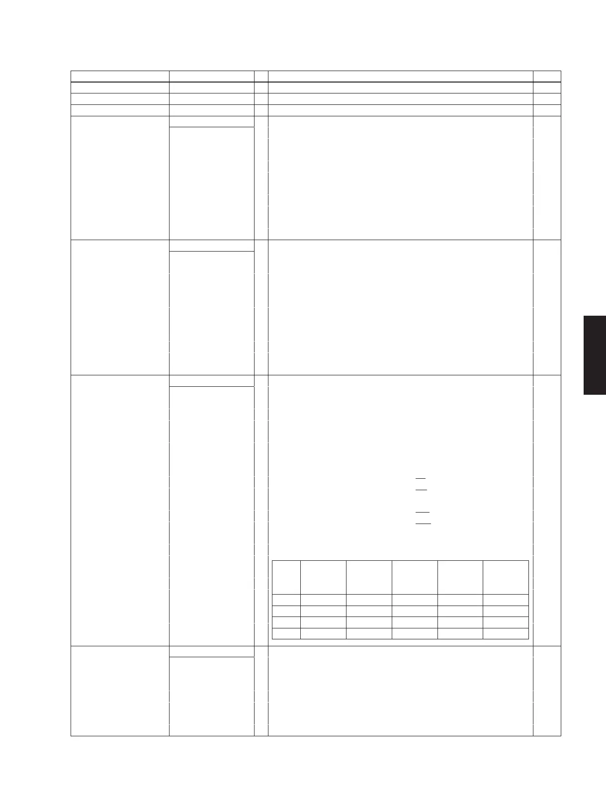
Pin No. Function Name I/O Detail of Function Option
5, 20, 40 VSS1, VSS2, VSS3 – - power supply No
8, 19 VDD1, VDD2 – + power supply No
39 VDD3 – USB reference voltage Yes
21, 22, 23, 24, 25, 26, 27, 28
Port 0
I/O
• 8-bit I/O ports
Ye s
P00 to P07
• I/O specifiable in 4-bit units
• Pull-up resistors can be turned on and off in 4-bit units
• HOLD reset input
• Port 0 interrupt input
• Pin functions
AD converter input ports : AN0 to AN7 (P00 to P07)
On chip debugger pins : DBGP0 to DBGP2 (P02 to P04)
P05 : System clock output/audio interface SDAT input/output
P06 : Timer 6 toggle output/audio interface BCLK input/output
P07 : Timer 7 toggle output/audio interface LRCK input/output
9, 10, 11, 12, 13, 14, 15, 16
Port 1
I/O
• 8-bit I/O ports
Ye s
P10 to P17
• I/O specifiable in 1-bit units
• Pull-up resistors can be turned on and off in 1-bit units
• Pin functions
P10 : SIO0 data output
P11 : SIO0 data input/bus input/output
P12 : SIO0 clock input/output
P13 : SIO1 data output
P14 : SIO1 data input/bus input/output
P15 : SIO1 clock input/output
P16 : Timer 1 PWML output
P17 : Timer 1 PWMH output/beeper output
29, 30, 31, 32, 33, 34, 35, 36
Port 2
I/O
• 8-bit I/O ports
Ye s
P20 to P27
• I/O specifiable in 1-bit units
• Pull-up resistors can be turned on and off in 1-bit units
• Pin functions
P20 to P23 : INT4 input/HOLD reset input/timer 1 event input/timer 0L capture input/
timer 0H capture input
P24 to P27 : INT5 input/HOLD reset input/timer 1 event input/timer 0L capture input/
timer 0H capture input
P20 : INT6 input/timer 0L capture 1 input
P22 : SIO4 data input/output/parallel interface RD output
P23 : SIO4 data input/output/parallel interface WR output
P24 : SIO4 clock input/output/lNT7 input/timer 0H capture 1 input
P25 : SIO9 data input/output/parallel interface RD9 output
P26 : SIO9 data input/output/parallel interface WR9 output
P27 : SIO9 clock input/output
Interrupt acknowledge types
41, 42, 43, 44, 45 Port 3 I/O • 5-bit I/O ports Ye s
P30 to P34 • I/O specifiable in 1-bit units
• Pull-up resistors can be turned on and off in 1-bit units
• Pin functions
P30 : UART1 transmit
P31 : UART1 receive
P33 : Audio interface PLL filter pin
P34 : USB interface PLL filter pin
Rising Falling
Rising
and
Falling
H level L level
INT4 enable enable enable disable disable
INT5 enable enable enable disable disable
INT6 enable enable enable disable disable
INT7 enable enable enable disable disable
 Loading...