30
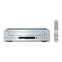
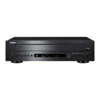
CD-C600
CD-C600
Pin No. Function Name I/O Detail of Function Option
1, 46, 47, 48 Port 7 I/O • 4-bit I/O port No
P70 to P73 • I/O specifiable in 1-bit units
• Pull-up resistors can be turned on and off in 1-bit units
• Pin functions
P70 : INT0 input/HOLD reset input/timer 0L capture input/watchdog timer output
P71 : INT1 input/HOLD reset input/timer 0H capture input
P72 : INT2 input/HOLD reset input/timer 0 event input/timer 0L capture input/high
speed clock counter input
P73 : INT3 input (input with noise filter)/timer 0 event input/timer 0H capture input/IR
remote control receiver input
AD converter input ports : AN8 (P70), AN9 (P71)
Interrupt acknowledge types
18 PWM0 I/O PWM0, PWM1 output port No
17 PWM1 General-purpose input port
• Pin functions
PWM0 : Audio interface master clock output
PWM1 : Audio interface master clock input
37 UHD- I/O USB data I/O pin UHD-/general-purpose I/O port No
38 UHD+ I/O USB data I/O pin UHD+/general-purpose I/O port No
2
RES I Reset pin No
3 XT1 I • 32.768 kHz crystal oscillator input No
• Pin functions
General-purpose input port
AD converter input ports : AN10
Must be connected to VDD1 when not to be used
4 XT2 I/O • 32.768 kHz crystal oscillator output No
• Pin functions
General-purpose I/O
AD converter input port : AN11
Must be set for oscillation and kept open if not to be used
6 CF1 I Ceramic/crystal resonator input No
7 CF2 I Ceramic/crystal resonator output No
Rising Falling
Rising
and
Falling
H level L level
INT0 enable enable disable enable enable
INT1 enable enable disable enable enable
INT2 enable enable enable disable disable
INT3 enable enable enable disable disable