CDX-E410
24
CDX-E410
Name
PORT_PLAY
PORT_STOP
PORT_PRE_STANDBY
PORT_STANDBY
DC voltage level
H
H x 2/3
H x 1/3
0
Content
The period between from playback operation to stop factor generation.
Playback operation: “PLAY” key operation, disc tray hand push close
Stop factor: “STOP”, “EJECT”, “STANDBY/ON” key operation
Playback contents end
Failsafe stop by abnormal detection
Power on state other than PORT_PLAY state
The period between from standby operation to standby process
completion and from CD reset start to initialize process completion
Standby state after standby process completion
■ SYSTEM CONTROL
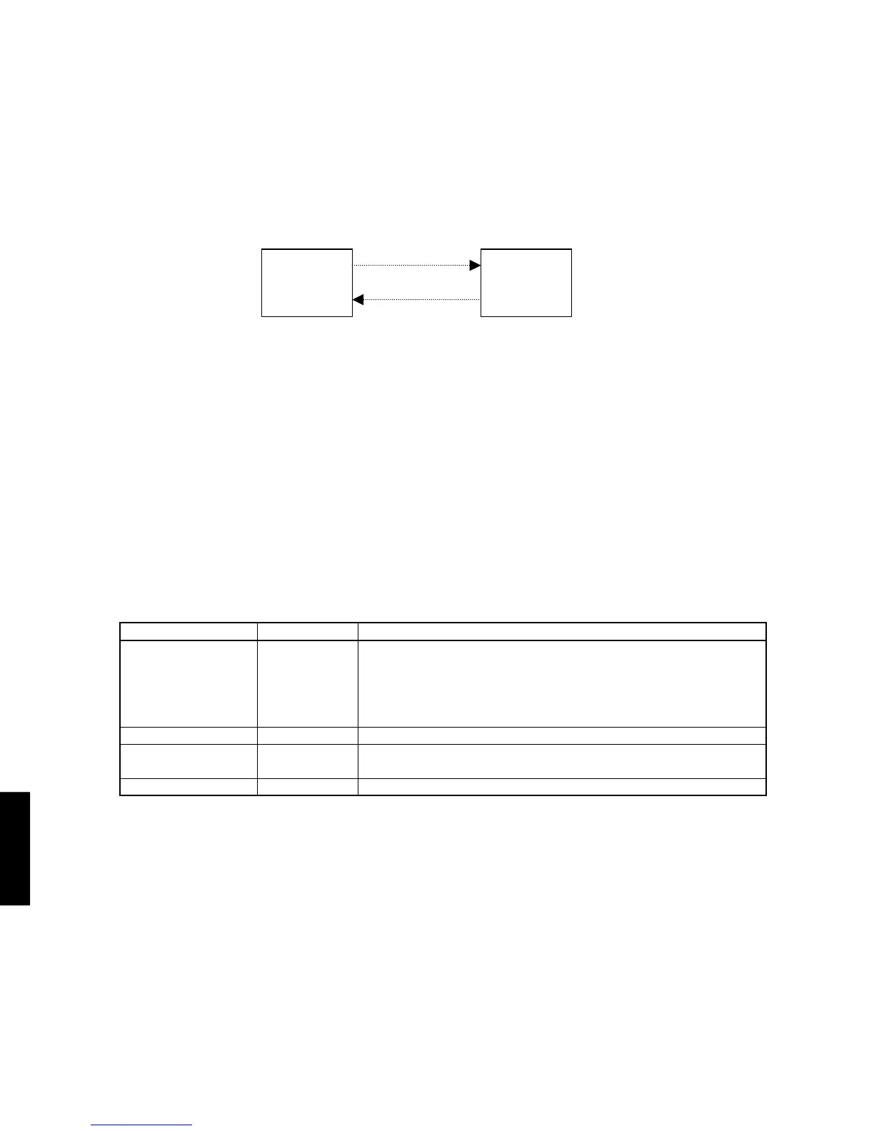
1. External Bus
1.1. Physical format of external bus
It is composed of 2 bus lines.
RX unit
(RX-E410) (CDX-E410)
MCR-E410
CD unit
RX command line
State info. line
1.2. Format of RX command
RX command is the request of RX to CD unit and the operation button code for CD.
Both are expressed by the remote control code of the NEC format. And the signal wave form is the demodulated
signal of remote control IR signal.
1.3. Format of state info.
State info. is the state information of CD and expressed by the DC voltage level.
H: Microprocessor Vcc level