DSP-AX2
DSP-AX2
24
bit7 MUTE requested
bit6 dts flashing (Red)
bit5 EX sound field being processed
bit4 Full mute (On: 1)
bit3 –
bit2 THROUGH & BYPASS (*2)
bit1 –
bit0 dts analog mute
5th byte
Indicates the information on the signal processing status.
(*2): In the case of digital signals other than 32kHz,
44.1kHz and 48kHz, through processing is
used for reproducible signals.
BSI 1 – 4: Bit stream information included in the DOLBY DIGITAL signal
indicated one by one.
11. IF STATUS
BSI1:0000000000
11. IF STATUS
BSI4:0000000000
CHS 1 – 4: IEC60958 channel status information of input signals
11. IF STATUS
CHS1:0299000200
11. IF STATUS
CHS5:0000000000
BDS 1 – 4: Bit stream information included in the dts signal indicated one by one.
YSS 1 – 3: Device status information of YSS928 (IC501)
* The numeric values in each example are for reference.
11. IF STATUS
BDS1:FFFFFFFFFF
11. IF STATUS
BDS4:FFFFFFFFFF
11. IF STATUS
YSS1:FE0218070F
11. IF STATUS
YSS2:0101418000
11. IF STATUS
YSS3:1A41803D
Byte No.
Function
1 YSS MUTE Reg
2 YSS MODE Reg
3 YSS IPORT BIT 7 – 0
4 YSS IPORT BIT 14 – 8
5 YSS OPORT
Byet No.
Function
1 IEC1937 Preamble Pc
2 AC-3 Data Stream No
3 AC-3D Decode Status
4 YSS ZERO Reg
5 MIREG
Byte No.
Function
1 DIR Status
2 DIR fs
3 DIR fs count
4 YSS ZEROBF
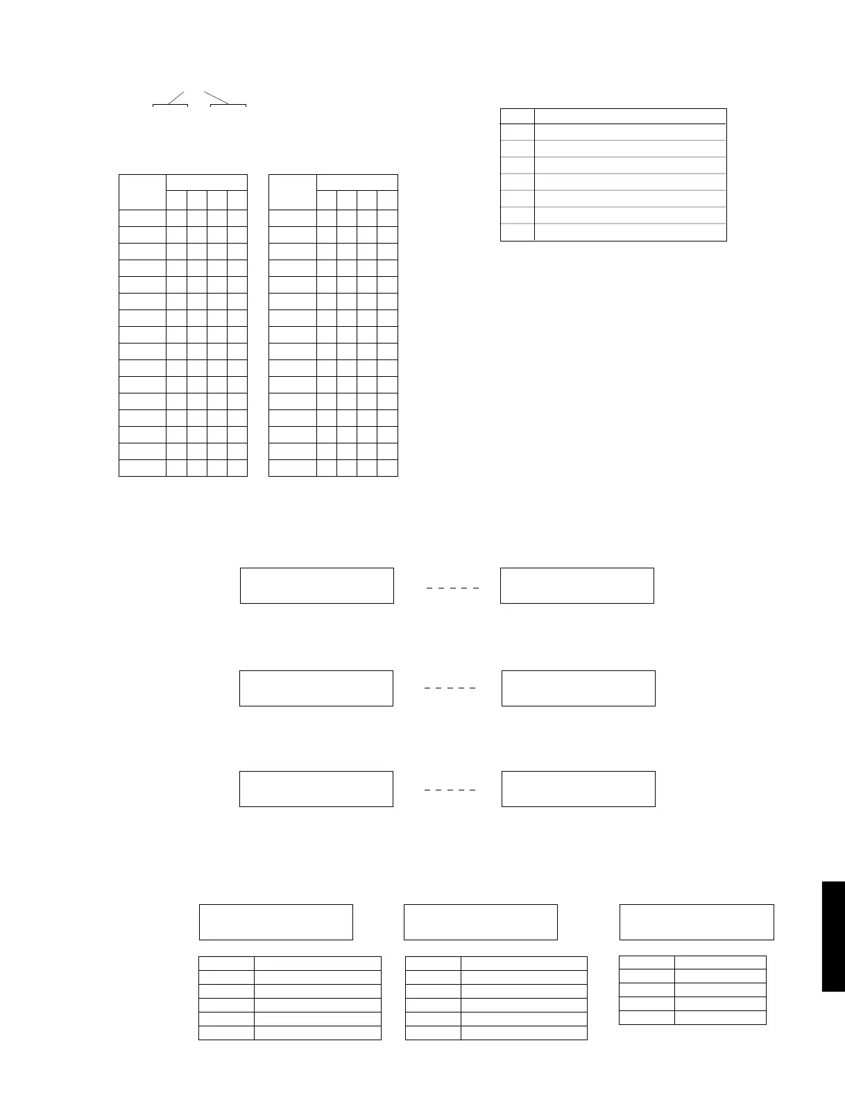
Indicate bit
7654
0 0000
1 0001
2 0010
3 0011
4 0100
5 0101
6 0110
7 0111
8 1000
9 1001
A 1010
B 1011
C 1100
D 1101
E 1110
F 1111
Indicate
0 0
0000 0000
bit 7654 3210
Indicate bit
3210
0 0000
1 0001
2 0010
3 0011
4 0100
5 0101
6 0110
7 0111
8 1000
9 1001
A 1010
B 1011
C 1100
D 1101
E 1110
F 1111
 Loading...