DSP-AX2
DSP-AX2
6
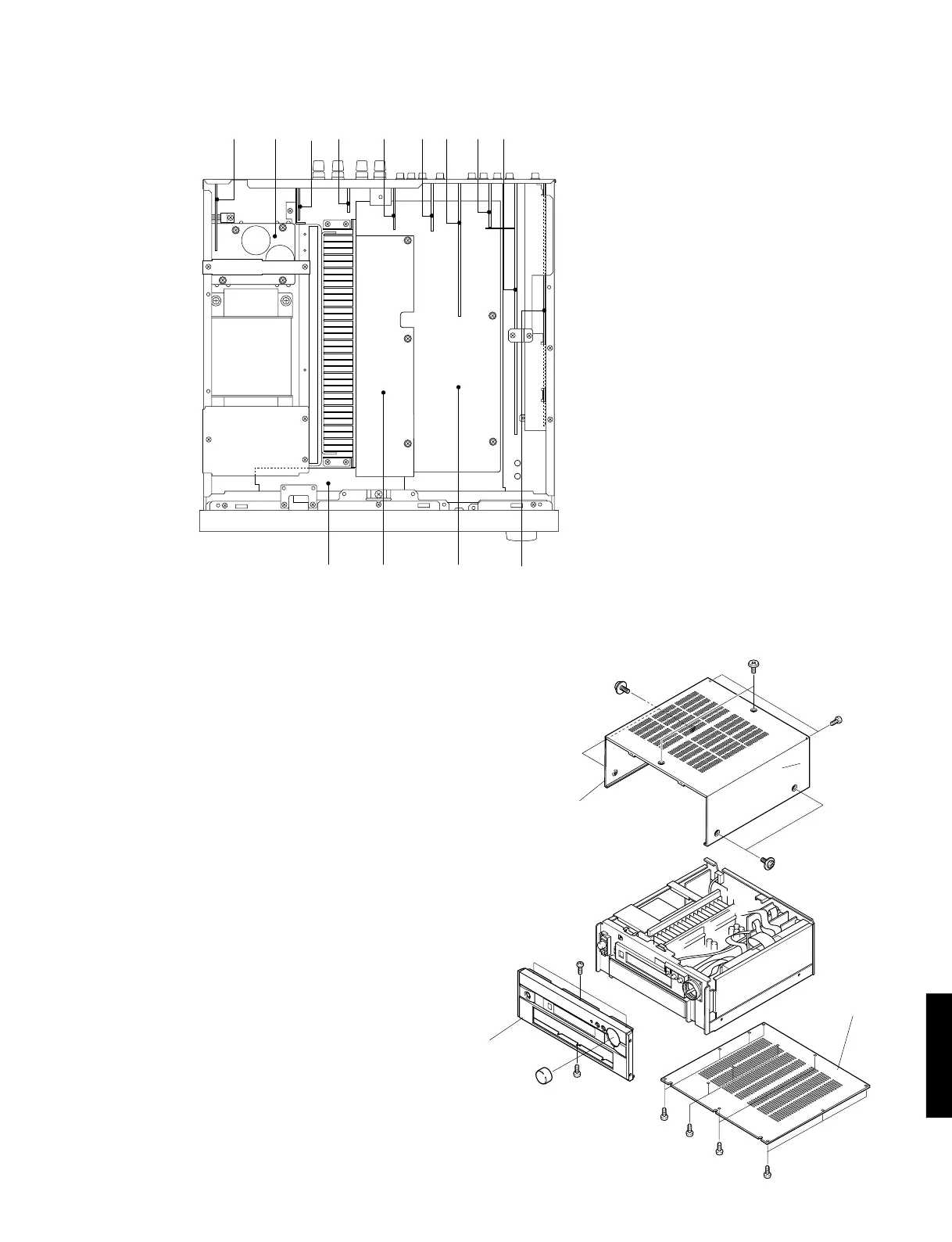
■ INTERNAL VIEW
■ DISASSEMBLY PROCEDURES
(Remove parts in the order as numbered.)
1. Removal of Top Cover
Remove 8 screws ( q, w and e ) and then remove
the Top Cover in Fig. 1.
2. Removal of Bottom Cover
a. Remove 13 screws ( r ) and then remove the Bottom
Cover in Fig. 1.
3. Removal of Front Panel
a. Remove a knob in Fig. 1.
b. Remove 4 screws ( t ) and then remove the Front
Panel in Fig. 1.
Fig. 1
q
w
e
r
r
r
r
t
t
Bottom Cover
Front Panel
Top Cover
q
q
qwe
t
ryuio
!0 !1 !2 !3
q F AMP (2) P.C.B.
w MAIN (2) P.C.B.
e MAIN (4) P.C.B.
r MAIN (5) P.C.B.
t VIDEO (3) P.C.B.
y VIDEO (2) P.C.B.
u VIDEO (1) P.C.B.
i VIDEO (4) P.C.B.
o FUNCTION P.C.B.
!0 OPERATION (2) P.C.B.
!1 F AMP (1) P.C.B.
!2 MAIN (1) P.C.B.
!3 DSP P.C.B.
 Loading...


