21
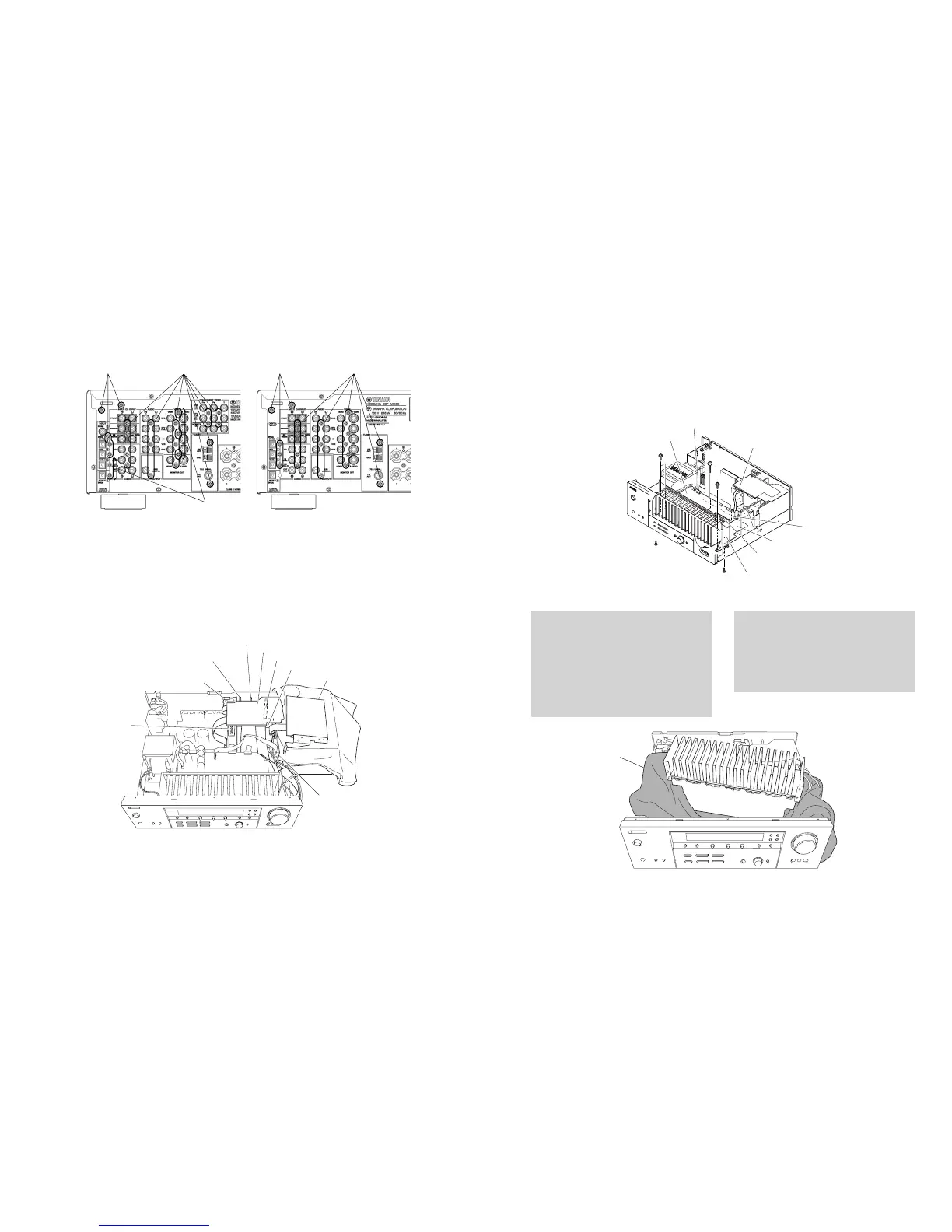
RX-V550/HTR-5750
RX-V450/HTR-5740/DSP-AX450
FUNCTION (3) P.C.B.
(HTR-5750, DSP-AX450 only)
DSPP. C . B .
FUNCTION (7) P.C.B.
(Except DSP-AX450)
FUNCTION (8) P.C.B.
FUNCTION (4) P.C.B.
FUNCTION (6) P.C.B.
FUNCTION (1) P.C.B.
FUNCTION (2) P.C.B.
Tuner
Cloth
布
CB354
CB351
CB503
MAIN (1) P.C.B.
MAIN (7) P.C.B.
MAIN (5) P.C.B.
POWER (1) P.C.B.
8
7
7
9
9
5 6 5 6
HTR-5750/RX-V450/HTR-5740 DSP-AX450
HTR-5750 only
Fig. 3
4. FUNCTION(1)〜(4)、(6)〜(8)、TUNERの外し方
a. CB307、CB351、CB502、CB503を外します。(Fig.2)
b. 6のネジ15本を外します。(Fig.3)
c. FUNCTION(1)〜(4)、(6)〜(8)、TUNERを取り外します。
(Fig.4)
4. Removal of FUNCTION (1), (2), (4), (6) ~ (8) P.C.B.s
and Tuner
a. Remove CB307, CB351, CB502 and CB503. (Fig. 2)
b. Remove 19 (HTR-5750), 16 (RX-V450, HTR-5740) screws
(6). (Fig. 3)
c. Remove FUNCTION (1), (2), (4), (6) ~ (8) P.C.B.s. and the
Tuner. (Fig. 4)
Fig. 4
5. MAIN(1)、MAIN(5)、MAIN(7)、POWER(1)P.C.B.の
外し方
a. CB351、CB354、CB503を外します。(Fig.5)
b. 7のネジ2本、8のネジ2本、9のネジ3本を外します。(Fig.5)
c. MAIN(1)、MAIN(5)、MAIN(7)、POWER(1)P.C.B.を取
り外します。(Fig.5)
5. Removal of MAIN (1), MAIN (5), MAIN (7) and
POWER (1) P.C.B.s
a. Remove CB351, CB354 and CB503. (Fig. 5)
b. Remove 2 screws (7), 2 screws (8) and 3 screws (9).
(Fig. 5)
c. Remove MAIN (1), MAIN (5), MAIN (7) and POWER (1)
P.C.B.s.. (Fig. 5)
P.C.B.チェックをする場合には
・ 布を敷きます。その上にMAIN(1)、(5)、(7)、POWER(1)
P.C.B.をヒートシンクと一 緒に 立て てチェックします。
・ 外したケーブル(コネクター)を すべ て 接続してください。
・フラットケーブルを接続する際、極性に注意してください。
・ リアパネルから外したP.C.B.はアースが浮いて動作しません
ので、各P.C.B.のアースをリード線等でシャーシまたはGND
に接続してください。
When checking the P.C.B.:
• Put a Cloth over the equipment. Put the MAIN (1), (5), (7)
and POWER (1) P.C.B.s together with the heat sink upright
on the Cloth and check them. (Fig. 6)
• Reconnect all cables (connectors) that have been
disconnected.
• When connecting the flat cable, use care for the polarity.
• The P.C.B. removed from the rear panel does not work
because its grounding is loose. Be sure to connect the
ground of each P.C.B. to the chassis or GND with a jumper
wire or the like.
Fig. 6
Fig. 5
 Loading...


