RX-V557/HTR-5850/DSP-AX557
RX-V457/HTR-5840/DSP-AX457
20
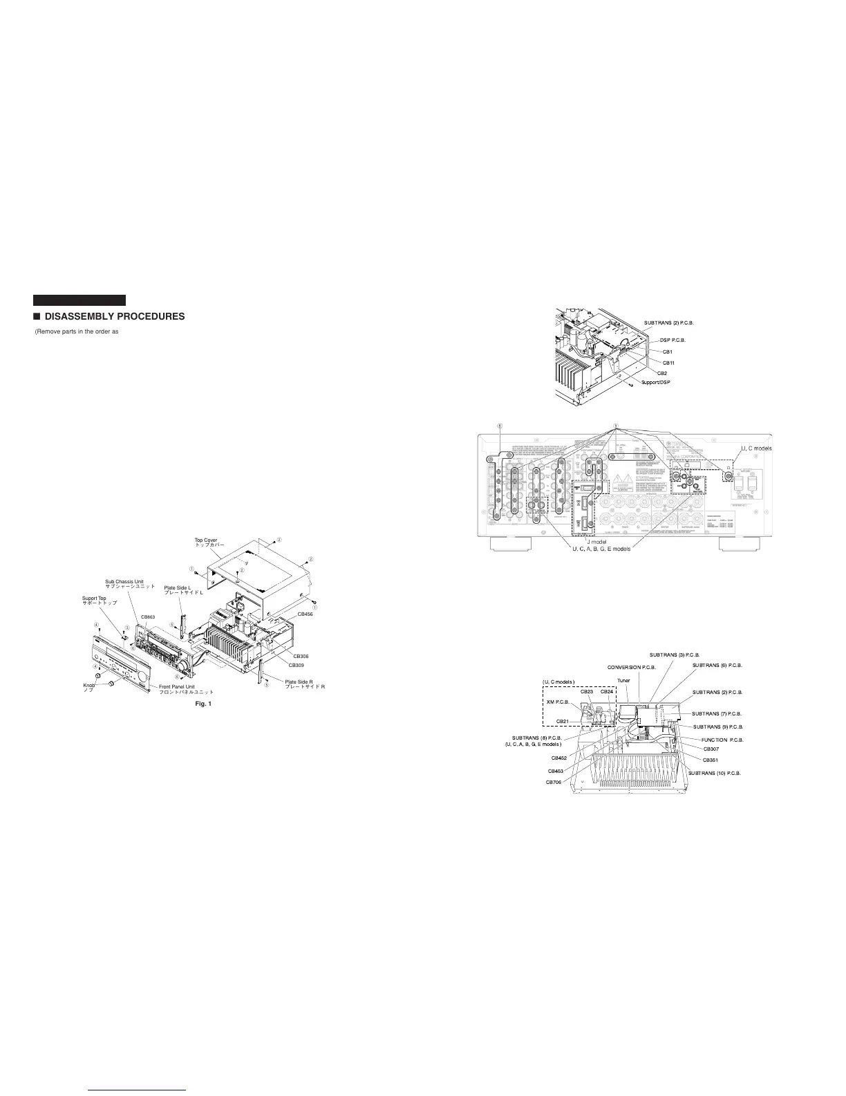
SUBTRANS (9) P.C.B.
SUBTRANS (10) P.C.B.
SUBTRANS (7) P.C.B.
SUBTRANS (2) P.C.B.
SUBTRANS (6) P.C.B.
SUBTRANS (3) P.C.B.
CONVERSION P.C.B.
FUNCTION P.C.B.
Tuner
XM P.C.B.
SUBTRANS (8) P.C.B.
(U, C, A, B, G, E models )
CB21
CB23 CB24
CB307
CB351
CB452
CB453
CB706
(U, C models )
1
1
2
2
2
CB309
CB306
CB456
Top Cover
トップカバー
Front Panel Unit
フロントパネルユニット
Knob
ノブ
Suport Top
サポートトップ
CB863
Sub Chassis Unit
サブシャーシユニット
Plate Side L
プレートサイドL
Plate Side R
プレートサイドR
3
4
4
5
5
6
6
■ DISASSEMBLY PROCEDURES
Fig. 1
(Remove parts in the order as numbered.)
Disconnect the power cable from the AC outlet.
1. Removal of Top Cover
a. Remove 4 screws (1) and 5 screws (2). (Fig. 1)
b. Slide the Top Cover rearward to remove it. (Fig. 1)
2. Removal of Front Panel Unit
a. Remove 2 Knobs. (Fig. 1)
b. Remove 1 screw (3) and then remove the Support Top. (Fig. 1)
c. Remove 6 screws (4) and then remove the Front Panel Unit.
(Fig. 1)
3. Removal of Plate Side
a. Remove 2 push rivets (5). (Fig. 1)
b. Remove the Plate Side L/R. (Fig. 1)
4. Removal of Sub Chassis Unit
a. Remove 2 screws (6) and then slide the Sub Chassis Unit
forward. (Fig. 1)
b. Loosen the harness fixture fixing the cable.
c. Remove CB306, CB309, CB456 and CB863 and then remove
the Sub Chassis Unit. (Fig. 1)
5. Removal of DSP P.C.B.
a. Remove 1 screw (7). (Fig. 2)
b. Remove 7 screws (8). (Fig. 3)
c. Remove CB2 and CB11. (Fig. 2)
d. Lift up the SUBTRANS (2) P.C.B. and remove the CB1. (Fig. 2)
e. Remove the DSP P.C.B. with the Support/DSP. (Fig. 2)
Fig. 3
6. Removal of FUNCTION, SUBTRANS (2), (3), (6), (7),
(8) (U, C, A, B, G, E models), (9), (10), CONVERSION,
XM (U, C models) P.C.B.s and Tuner
a. Remove CB21, CB23, CB24 (U, C models), CB307, CB351,
CB452, CB453 and CB706. (Fig. 4)
b. Remove 23 (U, C models) / 21 (A, B, G, E models) / 19 (R, T,
K, L models) screws (9). (Fig. 3)
c. Remove FUNCTION, SUBTRANS (2), (3), (6), (7), (8) (U, C, A,
B, G, E models), (9), (10), CONVERSION, XM (U, C models)
P.C.B.s and the Tuner. (Fig. 4)
RX-V557/DSP-AX557
(番号順に部品を取り外してください。)
AC電源コンセントから、電源コードを抜いてください。
1.トップカバーの外し方
a.
1
のネジ4本、
2
のネジ5本を外します。(Fig.1)
b. トップカバーを後方へスライドさせ、取り外します。(Fig.1)
2. フロントパネルユニットの外し方
a . ノブを 2 個取り外します。(Fig.1)
b.
3
のネジ1本を外し、サポートトッ プを 取り外します 。(Fig.1)
c.
4
のネジ6 本を外し、フロントパ ネル ユニットを取り外します。
(Fig.1)
3. プレート、サイドの外し方
a.
5
のプッシュリベット2 本を外します。(Fig.1)
b. プレートサイドL /Rを取り外します。(Fig.1)
4 . サブ シャーシユ ニットの外し方
a.
6
のネジ2本を外し、サブシャーシユニットを前方に引き出します。
(Fig.1)
b. ケーブルを固定している束線止めをゆるめます。
c. CB306、CB309、CB456、CB863を外し、サブシャーシユ
ニットを取り外します 。(Fig.1)
5. DSPP.C.B.の外し方
a.
7
のネジ1本を外します。(Fig.2)
b.
8
のネジ7本を外します。(Fig.3)
c. CB2、CB11を外します。(Fig.2)
d. SUBTRANS(2)P.C.B.を上部に浮かせCB1を外します。(Fig.2)
e. DSPP.C.B.をサポート/DSPと共に取り外します。(Fig.2)
6. FUNCTION、SUBTRANS(2)、(3)、(6)、(7)、(9)、(10)、
CONVERSIONP.C.B.、TUNERの外し方
a. CB307、CB351、CB452、CB453、CB706を外します。
(Fig.4)
b.
9
のネジ22本を外します。(Fig.3)
c. FUNCTION、SUBTRANS(2)、(3)、(6)〜(10)、
CONVERSIONP.C.B.、TUNERを取り外します。(Fig.4)
Fig. 2
 Loading...


