DSP-E800
DSP-E800
25
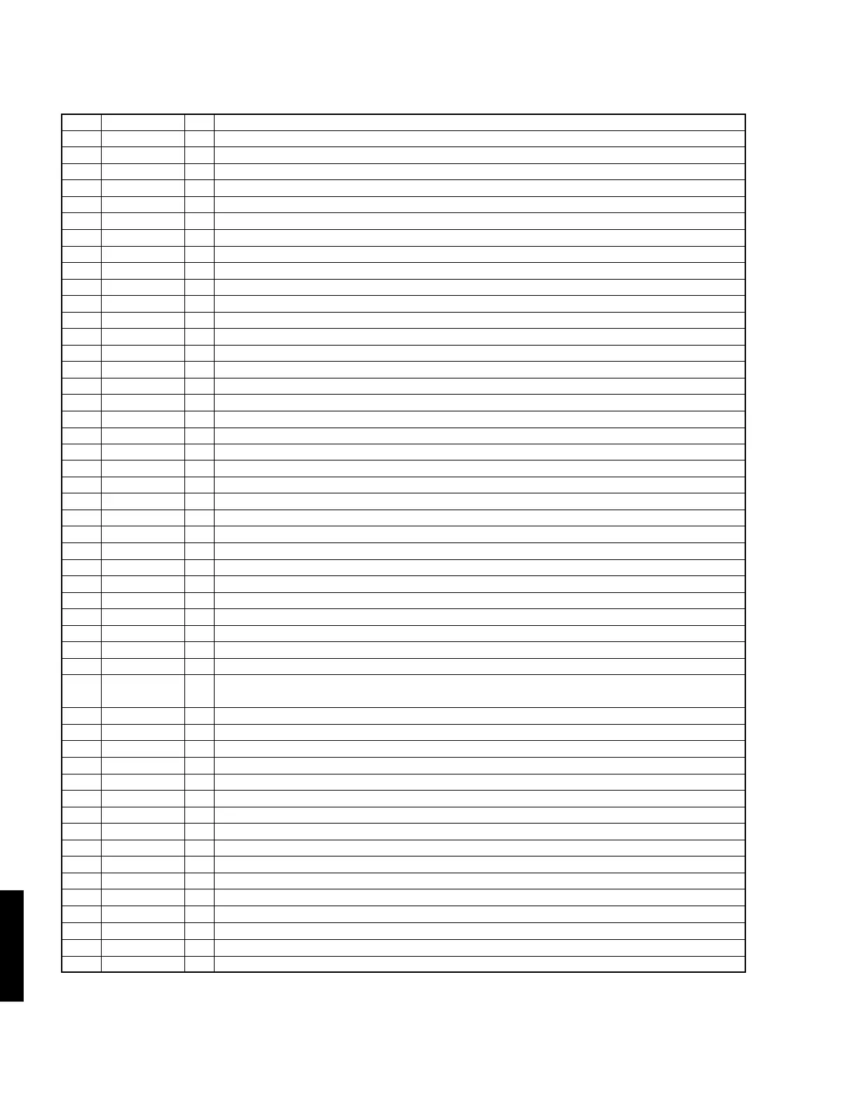
IC4 : YSS918D-F (AC3D2av)
DSP + AC-3(Dolby Digital)/ Pro Logic/ DTS Digital Surround Decoder
51 VDD2 +3V power supply
52 NONPCM O Non-PCM data output terminal, non-PCM data detect output
53 CRC O CRC output terminal (normally unconnected)
54 MUTE O Mute output terminal, connected to external microcomputer data mute detect input
55 KARAOKE O Karaoke output terminal (normally unconnected)
56 SURENC O Surround encoder output terminal (normally unconnected)
57 /SDBCK0 O Inverted signal of serial data bit clock output terminal 0 (normally unconnected)
58 RAMA6 O RAM address output terminal 6, connected to external 1M SRAM address
59 RAMA5 O RAM address output terminal 5, connected to external 1M SRAM address
60 VSS Ground
61 RAMA4 O RAM address output terminal 4, connected to external 1M SRAM address
62 /IC I Initial clear input terminal, connected to external output port expansion IC initial clear output
63 TEST Test terminal (normally unconnected)
64 RAMA3 O RAM address output terminal 3, connected to external 1M SRAM address
65 /CSB I Chip select B input terminal,connected to external microcomputer chip enable output 2
66 /CS I Chip select input terminal, connected to external microcomputer chip enable output 1
67 SO O Serial data output terminal, connected to external microcomputer serial data input
68 SI I Serial data input terminal, connected to external microcomputer serial data output
69 SCK I Serial clock input terminal, connected to external microcomputer serial clock output
70 RAMA2 O RAM address output terminal 2, connected to external 1M SRAM address
71 VDD1 +5V power supply
72 RAMD0 I/O RAM data bus terminal 0, connected to external 1M SRAM data
73 RAMD1 I/O RAM data bus terminal 1, connected to external 1M SRAM data
74 RAMD2 I/O RAM data bus terminal 2, connected to external 1M SRAM data
75 RAMD3 I/O RAM data bus terminal 3, connected to external 1M SRAM data
76 RAMD4 I/O RAM data bus terminal 4, connected to external 1M SRAM data
77 RAMD5 I/O RAM data bus terminal 5, connected to external 1M SRAM data
78 RAMD6 I/O RAM data bus terminal 6, connected to external 1M SRAM data
79 RAMD7 I/O RAM data bus terminal 7, connected to external 1M SRAM data
80 VSS Ground
81 VDD2 +3V power supply
82 SDWCK0 I Serial data word clock input terminal 0, connected to external DIR5 1fs word clock output
83 SDBCK0 I Serial data bit clock input terminal 0, connected to external DIR5 64fs bit clock output
84 SDIA0 I Serial data input A terminal 0, AC-3/DTS bit stream (or PCM) data input, connected to external DIR5
audio data output
85 SDIA1 I Serial data input A terminal 1, connected to external CODEC audio data output
86 RAMA1 O RAM address output terminal 1, connected to external 1M SRAM address
87 RAMA0 O RAM address output terminal 0, connected to external 1M SRAM address
88 RAMWEN O RAM write enable output terminal, connected to external 1M SRAM write enable
89 RAMOEN O RAM output enable output terminal, connected to external 1M SRAM output enable
90 VSS Ground
91 VDD +3V power supply
92 IPORT7 I Input expansion port terminal 7, DVD coaxial/optical select
93 IPORT6 I Input expansion port terminal 6, DBS coaxial/optical select
94 IPORT5 I Input expansion port terminal 5 (normally connected to ground)
95 IPORT4 I Input expansion port terminal 4, digital sampling frequency select (H:96kHz, L:Non 96kHz)
96 IPORT3 I Input expansion port terminal 3, Front mix select (H: Outside, L: Inside)
97 IPORT2 I Input expansion port terminal 2, RF select (H: Exist, L:None)
98 IPORT1 I Input expansion port terminal 1, DTS select (H: DTS (YSS918), L: Non DTS (YSS908))
99 IPORT0 I Input expansion port terminal 0, SRAM select (H: 1M, L: 256k)
No. Name I/O Function
100 VSS Ground