DSP-E800
DSP-E800
3
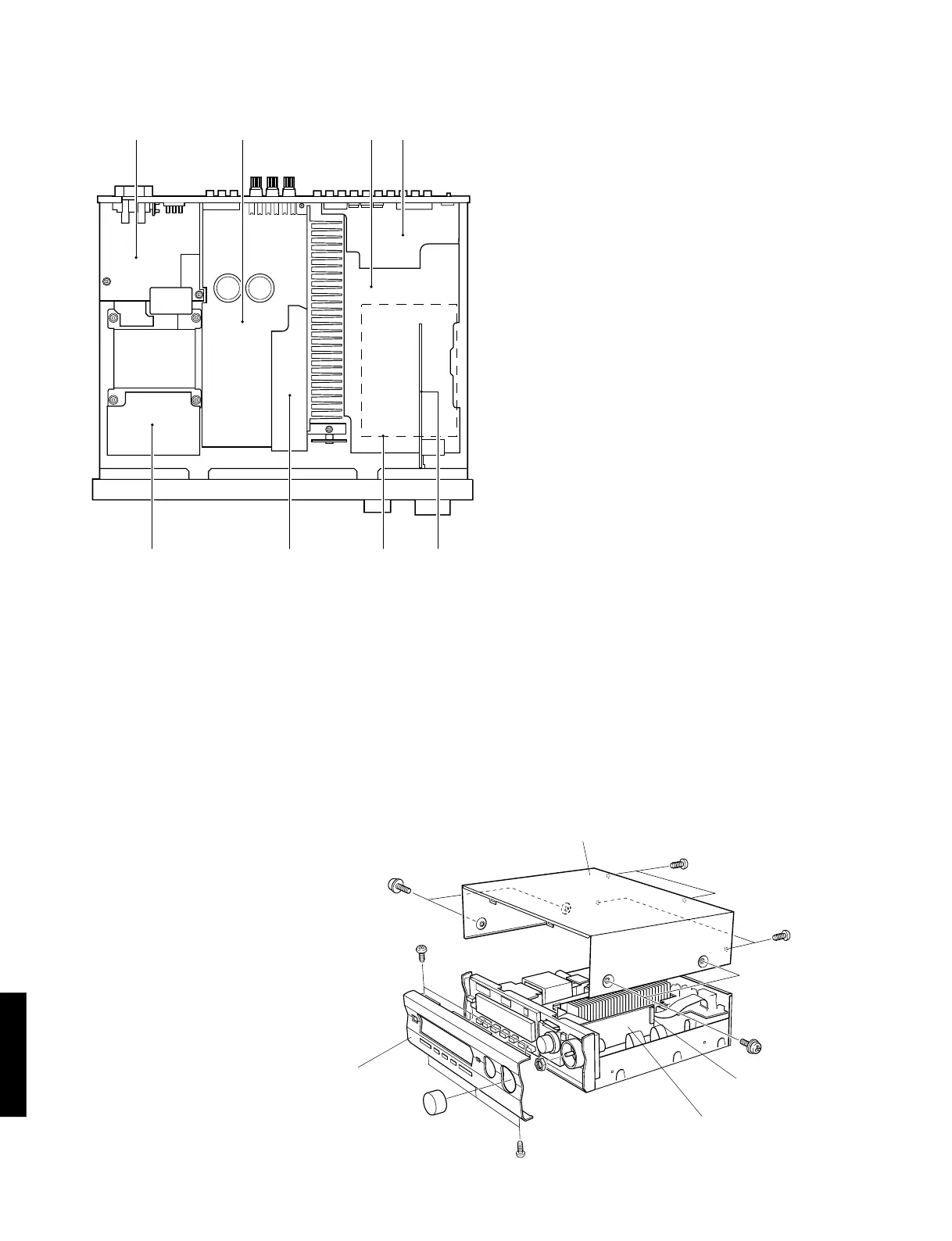
■ INTERNAL VIEW
q MAIN (2) P.C.B.
w MAIN (1) P.C.B.
e INPUT (1) P.C.B.
r INPUT (3) P.C.B.
t MAIN (5) P.C.B.
y MAIN (4) P.C.B.
u DSP P.C.B.
i OPERATION (2) P.C.B.
■ DISASSEMBLY PROCEDURES (Remove parts in disassembly order as numbered.)
1. Removal of Top Cover
a. Remove 4 screws (q) and 4 screws (w) in Fig. 1.
2. Removal of Front Panel
a. Remove 6 screws (e) in Fig. 1.
3. Removal of Operation (2) P.C.B.
a. Remove the Volume knob.
b. Disconnect a flat connecting cable (CB801) in Fig. 1.
c. Remove a nut (r) and then remove the Operation (2)
P.C.B. in Fig. 1.
Fig. 1
q e rw
t y u i
Top Cover
w
w
q
e
Front panel
q
e
r
Operation (2) P.C.B.
CB801