DSP-E800
DSP-E800
4
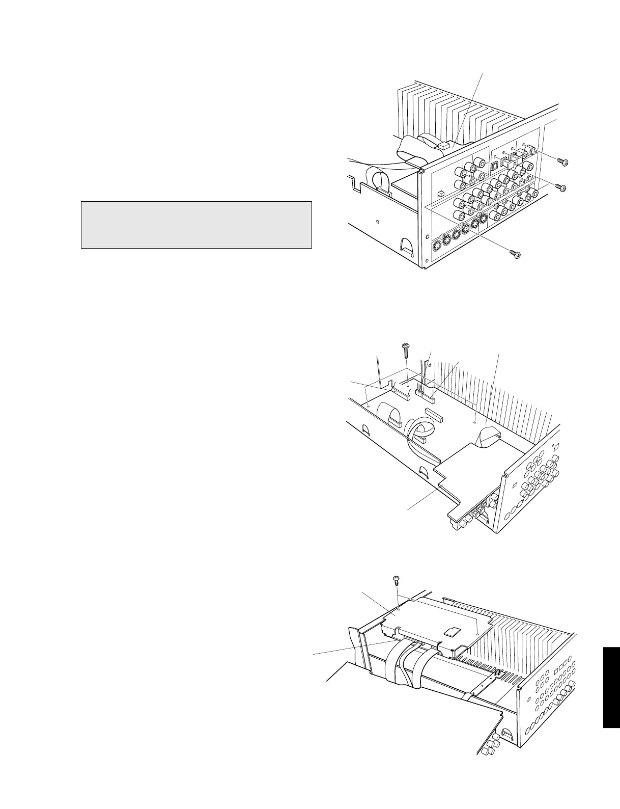
4. Removal of Input (3) P.C.B.
a. Remove 6 screws (t) and then remove the Input (3)
P.C.B. in Fig. 2.
5. Removal of Input (1) P.C.B.
a. Remove 6 screws (y) in Fig. 2.
b. Disconnect 2 flat connecting cables (CB402, CB406)
and a connector (CB410) in Fig. 3.
c. Remove 3 screws (u) and then remove the Input (1)
P.C.B. in Fig. 3.
Fig. 3
Fig. 2
Fig. 4
t
y
t
u
i
Shield Case/Top
DSP P.C.B.
Input (1) P.C.B.
CB402
CB406
Input (3) P.C.B.
6. Removal of DSP P.C.B.
a. Remove 2 screws (i) and then remove the Shield
Case/Top with the DSP P.C.B. in Fig. 4.
Note :
1.When the rear panel has been removed, the ground
connection at the input/output pin jack becomes open.
Connect it to the chassis by using a lead wire.
Input (3) P.C.B.
CB410