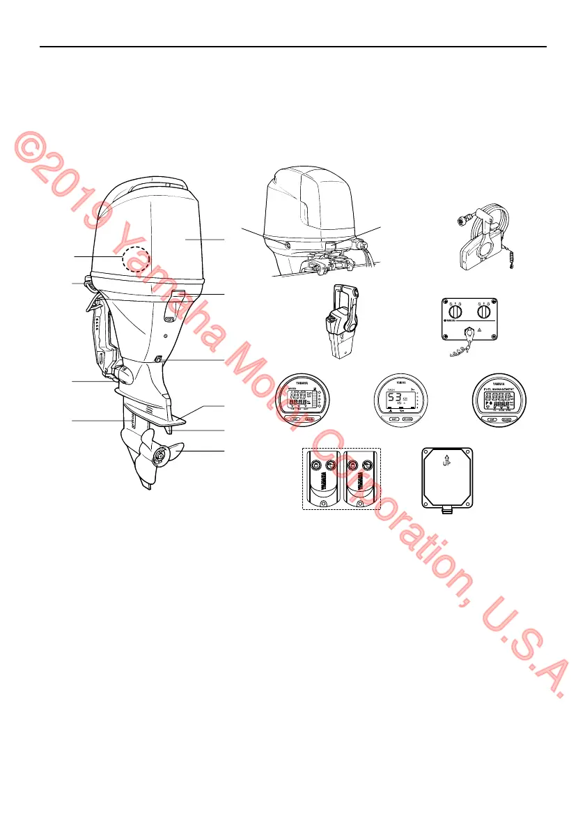
Components
30
EMU2579Y
Components diagram
IP:
* May not be exactly as shown; also may not be included as standard equipment on all models
(order from dealer).
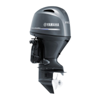
F115, LF115, F115A1, FL115A1
1
2
2
3
4
5
6
7
8
9
11
12
13 14
15 16 17
10
1918
ZMU07387
1. Top cowling
2. Cowling lock lever(s)
3. Drain screw
4. Anti-cavitation plate
5. Trim tab (anode)
6. Propeller*
7. Cooling water inlet
8. Anode
9. Flushing device
10.Water separator
11.Power trim and tilt switch
12.Remote control box (side mount type)*
13.Remote control box (binnacle mount type)*
14.Switch panel (for use with binnacle type)*
15.Digital speedometer*
16.Digital tachometer*
17.Fuel management meter*
18.Remote control transmitter*
19.Receiver*
U63P1DE0.book Page 30 Tuesday, March 29, 2011 7:15 PM
©2019 Yamaha Motor Corporation, U.S.A.