EasyManua.ls Logo

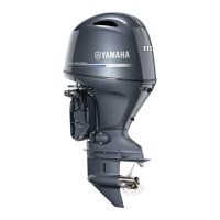
Yamaha F115A Service Manual

Yamaha F115A
709 pages
To Next Page IconTo Next Page
Page #1 background imageLoading...
Page #1 background image
SERVICE MANUAL
68V-28197-ZA-C1
WORLDWIDE
F115A
FL115A
F115Y
LF115Y
USA, CANADA
MANUEL D’ENTRETIEN
WARTUNGSHANDBUCH
MANUAL DE SERVICIO
E
F
D
ES
290381

Table of Contents

Other manuals for Yamaha F115A

Questions and Answers:

Yamaha F115A Specifications

General IconGeneral
Compression Ratio10.0:1
Fuel Induction SystemEFI (Electronic Fuel Injection)
Lubrication SystemWet sump
Ignition SystemTCI (Transistor Controlled Ignition)
Starting SystemElectric
Alternator Output35 Amp
Cooling SystemWater-cooled
SteeringRemote
Engine Type4-stroke, DOHC, 16-valve
Displacement1832 cc
Max. Power Output115 hp
Operating Range5300 - 6300 rpm
Full Throttle RPM Range5300 - 6300 rpm
Recommended FuelRegular Unleaded
Gear Ratio2.15:1
Shaft Length20 in (508 mm) / 25 in (635 mm)
Recommended OilYamalube 4M
ExhaustThrough prop
Oil Pan Capacity4.5 liters

Summary

CHAPTER 1 GENERAL INFORMATION

IDENTIFICATION

Locates and identifies the outboard motor's serial number stamped on a label.

SAFETY WHILE WORKING

Provides procedures recommended by Yamaha for safe maintenance and repair operations.

CHAPTER 2 SPECIFICATIONS

MAINTENANCE SPECIFICATIONS

Lists maintenance specifications for the power unit, cylinders, pistons, and rings.

CHAPTER 3 PERIODIC INSPECTIONS AND ADJUSTMENTS

MAINTENANCE INTERVAL CHART

Guide to general maintenance intervals, adaptable to operating conditions.

FUEL SYSTEM

Procedures for checking fuel lines, filters, and pressure.

CONTROL SYSTEM

Checks and adjustments for throttle body pickup timing, cables, and sensors.

POWER UNIT

Checks related to engine oil level, oil filter replacement, and timing belt.

CHAPTER 4 FUEL SYSTEM

HIGH-PRESSURE FUEL LINE

Procedures for removing/installing and reducing pressure in the high-pressure fuel line.

CHAPTER 5 POWER UNIT

FLYWHEEL MAGNET ASSEMBLY

Procedures for removing, installing, and disassembling the flywheel magnet assembly.

TIMING BELT

Procedures for removing, installing, and adjusting the timing belt and tensioner.

CYLINDER HEAD ASSEMBLY

Procedures for removing, installing, and checking the cylinder head assembly and thermostat.

CRANKSHAFT AND PISTON/CONNECTING ROD ASSEMBLY

Procedures for removing, installing, and checking crankshaft, piston, and connecting rod components.

CHAPTER 6 LOWER UNIT

BACKLASH (REGULAR ROTATION MODELS)

Procedures for measuring and adjusting forward and reverse gear backlash.

BACKLASH (COUNTER ROTATION MODELS)

Procedures for measuring and adjusting forward and reverse gear backlash.

CHAPTER 7 BRACKET UNIT

POWER TRIM AND TILT UNIT

Procedures for removing, installing, filling, and bleeding the power trim and tilt unit.

CHAPTER 8 ELECTRICAL SYSTEMS

WIRE HARNESS

Provides a wiring diagram and color codes for connections.

ELECTRICAL COMPONENTS ANALYSIS

Details procedures for using a digital circuit tester and measuring voltage and resistance.

IGNITION SYSTEM

Procedures for checking battery, fuses, ignition coil, spark gap, and peak voltage.

IGNITION CONTROL SYSTEM

Checks for battery, fuses, pulser coil, ECM, and throttle position sensor.

STARTING SYSTEM

Procedures for checking battery, fuses, starter relay, and starter motor components.

CHAPTER 9 TROUBLE ANALYSIS

TROUBLE ANALYSIS

Provides a chart for diagnosing common engine problems.

TROUBLE SHOOTING FOR ELECTRIC FUEL INJECTION

Troubleshooting steps for common electric fuel injection issues.

Related product manuals