6-7
E
LOWR
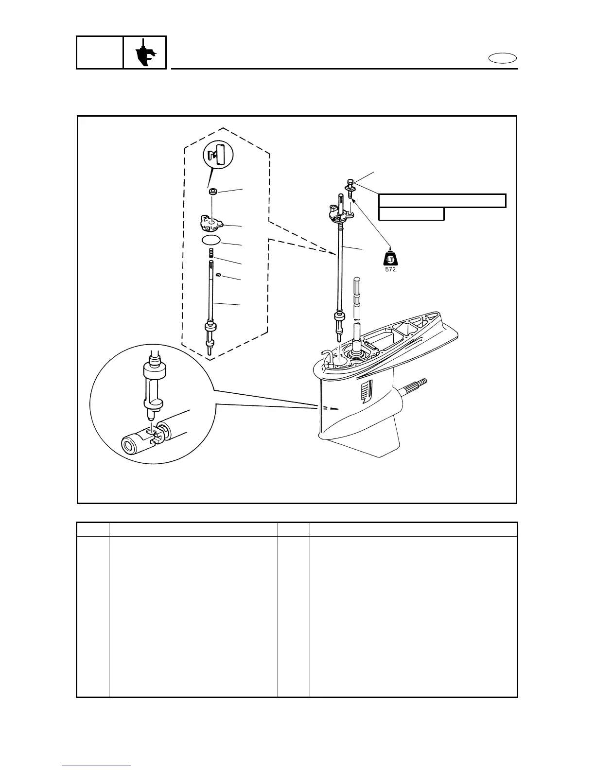
SHIFT ROD ASSEMBLY
(REGULAR ROTATION MODELS)
SHIFT ROD ASSEMBLY (REGULAR ROTATION MODELS)
6
REMOVING/INSTALLING THE SHIFT ROD ASSEMBLY
6
Order Job/Part Q’ty Remarks
Impeller plate Refer to “WATER PUMP (REGULAR
ROTATION MODELS)” on page 6-4.
1 Bolt 3 (with washer)
2 Shift rod assembly 1
3 Oil seal housing 1
4 Oil seal 1
5 O-ring 1
6 Spring 1
7 Shift rod 1
8 Circlip 1
For installation, reverse the removal
procedure.
4
3
5
6
8
7
2
1
8 Nm (0.8 m
•
kgf, 5.8 ft
•
Ib)
6 × 20 mm
6070