3-10
E
INSP
ADJ
CONTROL SYSTEM
ADJUSTING THE THROTTLE
POSITION SENSOR
(WHEN DISASSEMBLING OR
REPLACING THE THROTTLE BODY)
3
Adjusting steps
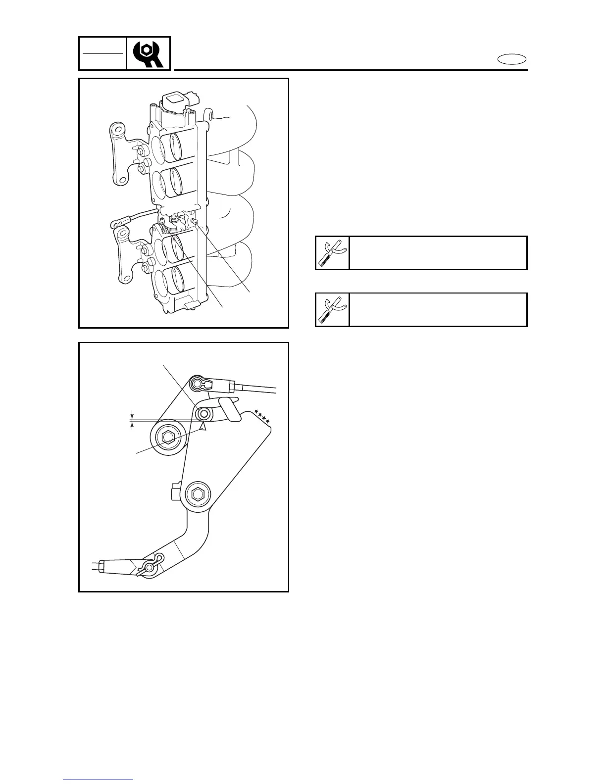
(1) Install the intake assembly with the
intake silencer removed.
(2) Disconnect the throttle position sensor
coupler.
(3) Install the test harness to the throttle
position sensor coupler.
(4) Connect the digital circuit tester.
(5) Turn the main switch to on.
(6) Loosen the synchronizing screw and
fully open the lower side throttle valve
(#3, 4).
(7) Loosen the idling screw 1 and fully
close the upper side throttle valve (#1,
2).
(8) Adjust the position of the throttle posi-
tion sensor until the output voltage is
0.7 ± 0.01 V and operate the throttle
valve several times.
(9) Record the value.
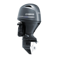
(10) Slowly tighten the synchronizing
screw 2 until the recorded value is
changed.
(11) Slowly tighten the idling screw until
0.032 ± 0.004 V increase over the
recorded value.
(12) Operate the throttle valve several
times.
(13) Install the throttle roller d as the mark
e aligns with center of the throttle
roller and check that the output volt-
age is not change.
(14) Install the intake silencer.
(15) Start the engine.
(16) If the output voltage of the throttle
position sensor is not within 0.732 ±
0.014 V, adjust the throttle position
sensor.
(17) Check that the throttle valve is syn-
chronized.
Test harness
90890-06793
Digital tester
J-39299 / 90890-06752
3162
1
2
d
e
3163