5-30
POWR
E
VALVES
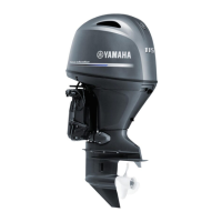
(2) Install the new valve guide to the spec-
ified position (from the top of the valve
guide bore as shown) a with the valve
guide remover/installer.
(3) After installing the valve guide, bore
the valve guide with the valve guide
reamer.
NOTE:
• Heat the cylinder head in an oven to 200˚C
(392˚F) to ease valve guide removal and
installation, and to maintain the correct
interference fit.
• Before installing the valve guide, mark its
installation position b as shown.
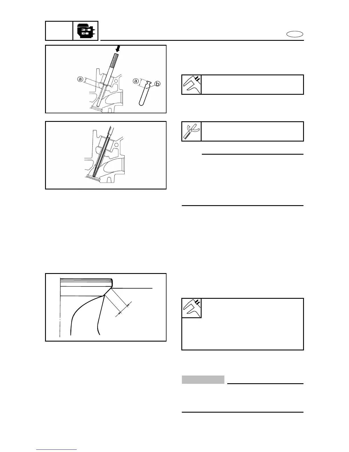
CHECKING THE VALVE SEAT 5
1. Measure:
• Valve seat width a
Out of specification → Reface the
valve seat.
2. Reface:
• Valve seat
CAUTION:
To prevent chatter marks, turn the valve
seat cutter while an even, downward pres-
sure (4 - 5 kg).
Valve guide position
11.5 mm (0.45 in)
Valve guide reamer
YM-04066 / 90890-04066
Valve seat width
Intake
1.58 - 1.94 mm
(0.062 - 0.076 in)
Exhaust
1.80 - 2.02 mm
(0.071 - 0.080 in)
5380
5390
a
5400
 Loading...