5-23
POWR
E
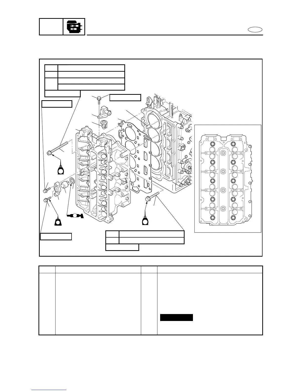
CYLINDER HEAD ASSEMBLY 5
REMOVING/INSTALLING THE CYLINDER HEAD ASSEMBLY 4
Order Job/Part Q’ty Remarks
Camshafts Refer to “CAMSHAFTS” on page 5-21.
Intake assembly Refer to “INTAKE ASSEMBLY” on
page 4-3.
1 Bolt (1.5 mm thread pitch) 10
2 Bolt 5
3 Cylinder head assembly 1
4 Gasket 1
5 Dowel pin 2
Continued on next page.
*: Torque value (for reference only)
8
4
1
5
9
0
E
6
C
B
A
3
B
D
7
15 Nm (1.5 m • kgf, 11 ft • Ib)1st
30 Nm (3.0 m • kgf, 22 ft • Ib)2nd
10 × 145 mm
6 × 25 mm
8 × 25 mm
6 × 20 mm
8 × 55 mm
14 Nm (1.4 m • kgf, 10 ft • Ib)1st
28 Nm (2.8 m • kgf, 20 ft • Ib)2nd
E
1
9
12
10
11
13
6
7
8
3
4
5
2
LTLT
LT
572
572
A
90°
3rd
70 Nm (7.0 m • kgf, 51 ft • Ib)*
E
5270
Not reusable
CYLINDER HEAD ASSEMBLY