4-3
FUEL
E
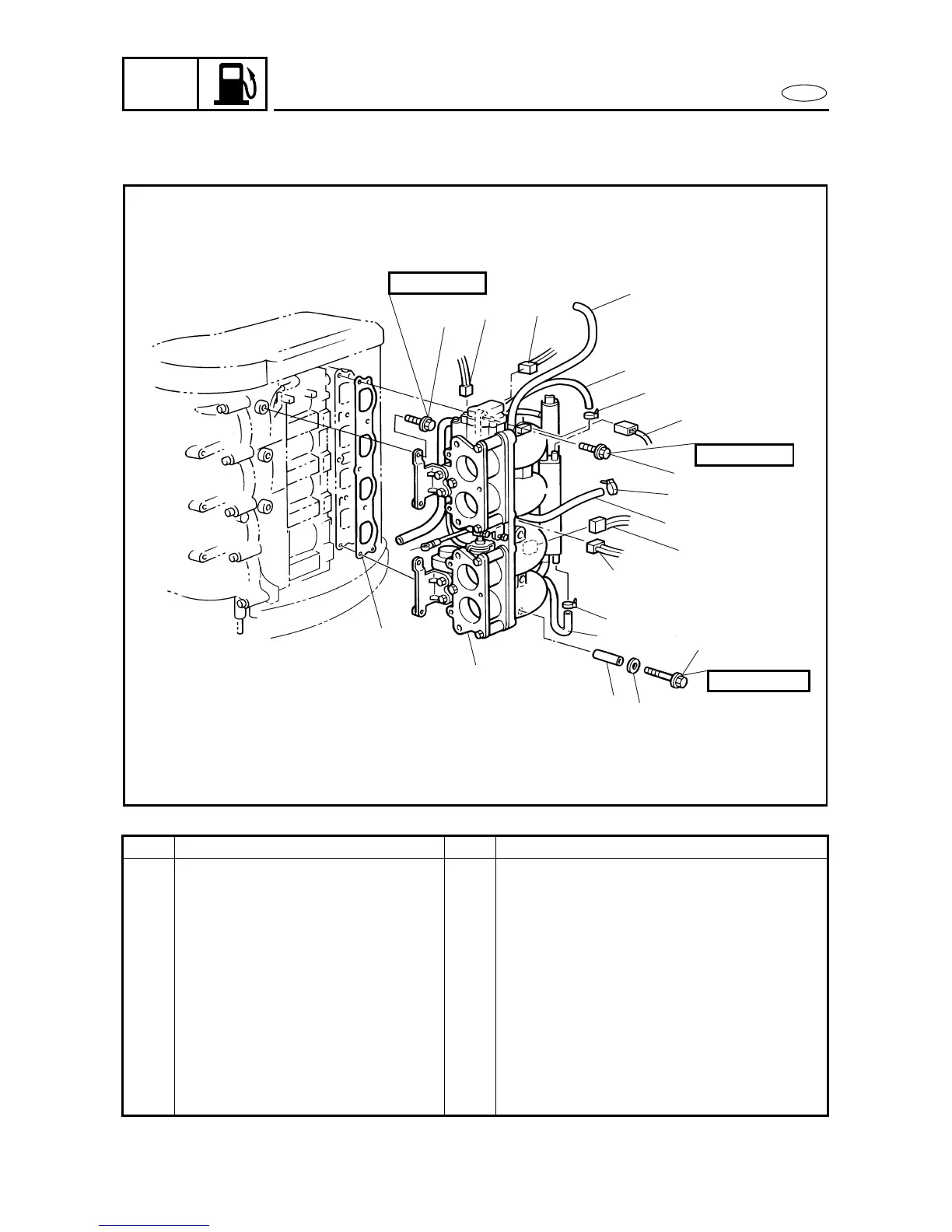
INTAKE ASSEMBLY
4
REMOVING/INSTALLING THE INTAKE ASSEMBLY
4
Order Job/Part Q’ty Remarks
Intake silencer Refer to “INTAKE SILENCER” on page
4-1.
1 Throttle joint link rod 1
2 Throttle position sensor coupler 1
3 Idle speed control valve coupler 1
4 Atmospheric pressure sensor
coupler
1
5 Fuel injector coupler 4
6 High-pressure fuel pump coupler 1
7 Bolt 4
8 Bolt 4
Continued on next page.
4010
7
3
2
17
15
14
4
8
12
5
6
9
10
11
14
16
1
8 × 40 mm
8 × 120 mm
6 × 20 mm
18
13
19
INTAKE ASSEMBLY