8-8
–+
ELEC
E
ELECTRICAL COMPONENTS ANALYSIS
ELECTRICAL COMPONENTS
ANALYSIS
8
DIGITAL CIRCUIT TESTER 8
NOTE:
“ ” indicates a continuity of electric-
ity which means a closed circuit at the
respective switch position.
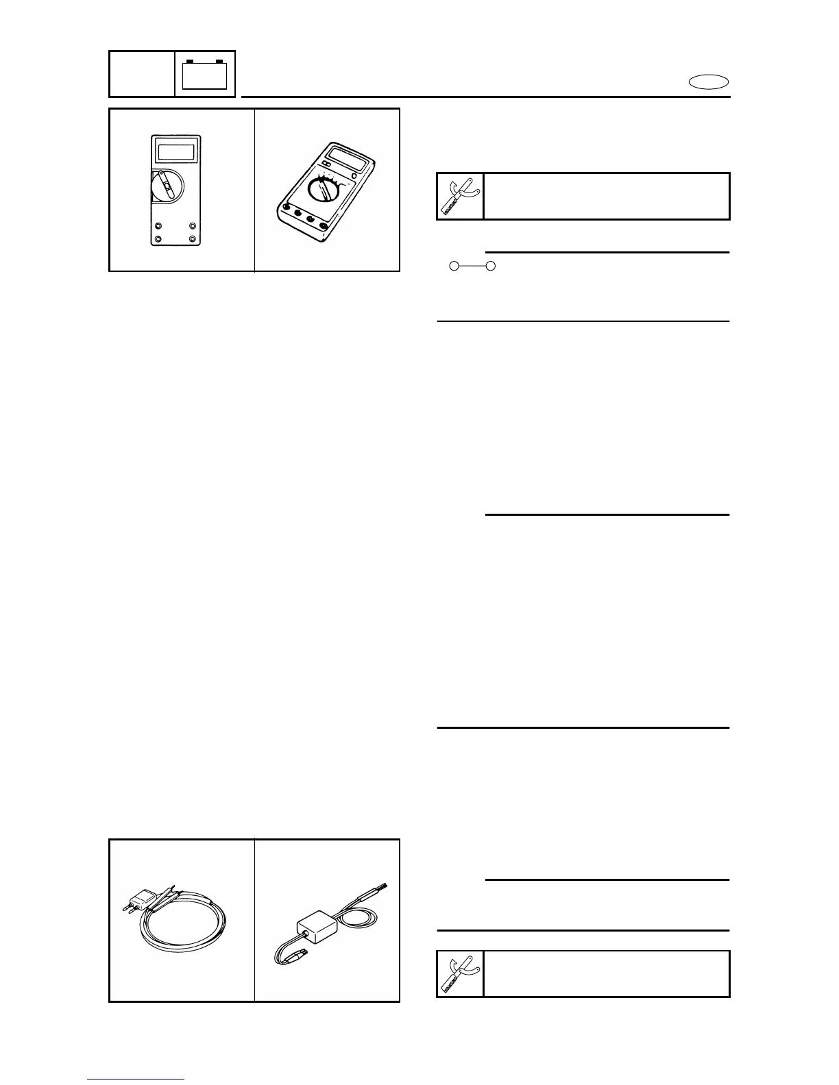
Digital tester
J-39299 / 90890-06752
8080
MEASURING THE PEAK VOLTAGE 8
NOTE:
• When checking the condition of the igni-
tion system it is useful to know the peak
voltage.
• Cranking speed is dependant on many
factors (e.g., fouled or weak spark plugs, a
weak battery). If one of these is defective,
the peak voltage will be lower than speci-
fication.
• If the peak voltage measurement is not
within specification the engine will not
operate properly.
PEAK VOLTAGE ADAPTOR 8
NOTE:
The peak voltage adaptor should be used
with the digital circuit tester.
Peak voltage adaptor
YU-39991 / 90890-03169
8090