4-23
FUEL
E
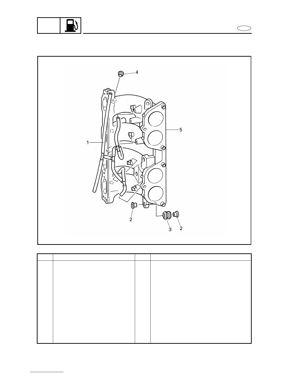
INTAKE MANIFOLD
INTAKE MANIFOLD
4
DISASSEMBLING/ASSEMBLING THE INTAKE MANIFOLD 4
Order Job/Part Q’ty Remarks
Throttle body Refer to “THROTTLE BODY” on page 4-5.
High-pressure fuel line Refer to “HIGH-PRESSURE FUEL LINE”
on page 4-8.
Idle speed control assembly Refer to “IDLE SPEED CONTROL
ASSEMBLY” on page 4-19.
1 Hose 1 (pressure regulator-to-intake manifold-to-
idle speed control assembly)
2 Collar 6
3 Grommet 3
4 Rubber seal 4
5 Intake manifold 1
For assembly, reverse the disassembly
procedure.
4180