8-9
–+
ELEC
E
ELECTRICAL COMPONENTS ANALYSIS
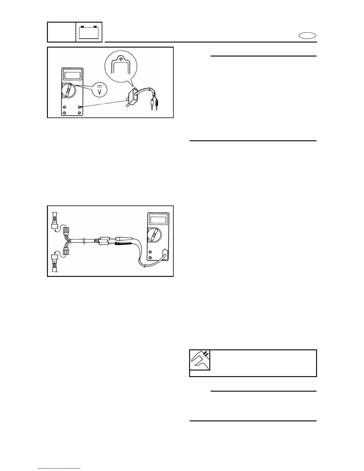
NOTE:
• When measuring the peak voltage, set the
selector to the DC voltage mode.
• Make sure the peak voltage adaptor leads
are properly installed in the digital tester.
• Make sure the positive pin (the “+” mark
facing up as shown) on the peak voltage
adaptor is installed into the positive termi-
nal of the digital tester.
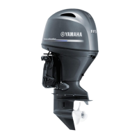
• The test harness is needed for the follow-
ing tests.
8100
Measuring steps
(1) Disconnect the coupler connections.
(2) Connect the test harness between the
couplers.
(3) Connect the peak voltage adaptor
probes to the connectors which are
being checked.
(4) Start or crank the engine and observe
the measurement.
8110
MEASURING A LOW RESISTANCE 8
When measuring a resistance of 10 Ω or
less with the digital tester, the correct mea-
surement cannot be obtained because of
the tester’s internal resistance.
To obtain the correct value, subtract the
internal resistance from the displayed mea-
surement.
NOTE:
The internal resistance of the digital tester
can be obtained by connecting both of its
probes.
Correct value
Displayed measurement –
internal resistance