8-13
–+
ELEC
E
IGNITION SYSTEM
MEASURING THE IGNITION SYSTEM
PEAK VOLTAGE
8
WARNING
When checking the peak voltage do not
touch any of the connections of the digital
tester lead wires.
NOTE:
• If there is no spark or the spark is weak,
continue with the ignition system test.
• If a good spark is obtained, the problem is
not with the ignition system, but possibly
with the spark plug(s) or another compo-
nent.
1. Measure:
NOTE:
• The peak voltage adaptor should be used
with the digital circuit tester.
• When measuring the peak voltage, set the
selector to the DC voltage mode.
• ECM unit output peak voltage
Below specification → Check the wire
harness.
Correct the wire harness → Replace
the ECM unit.
Peak voltage adaptor
YU-39991 / 90890-03169
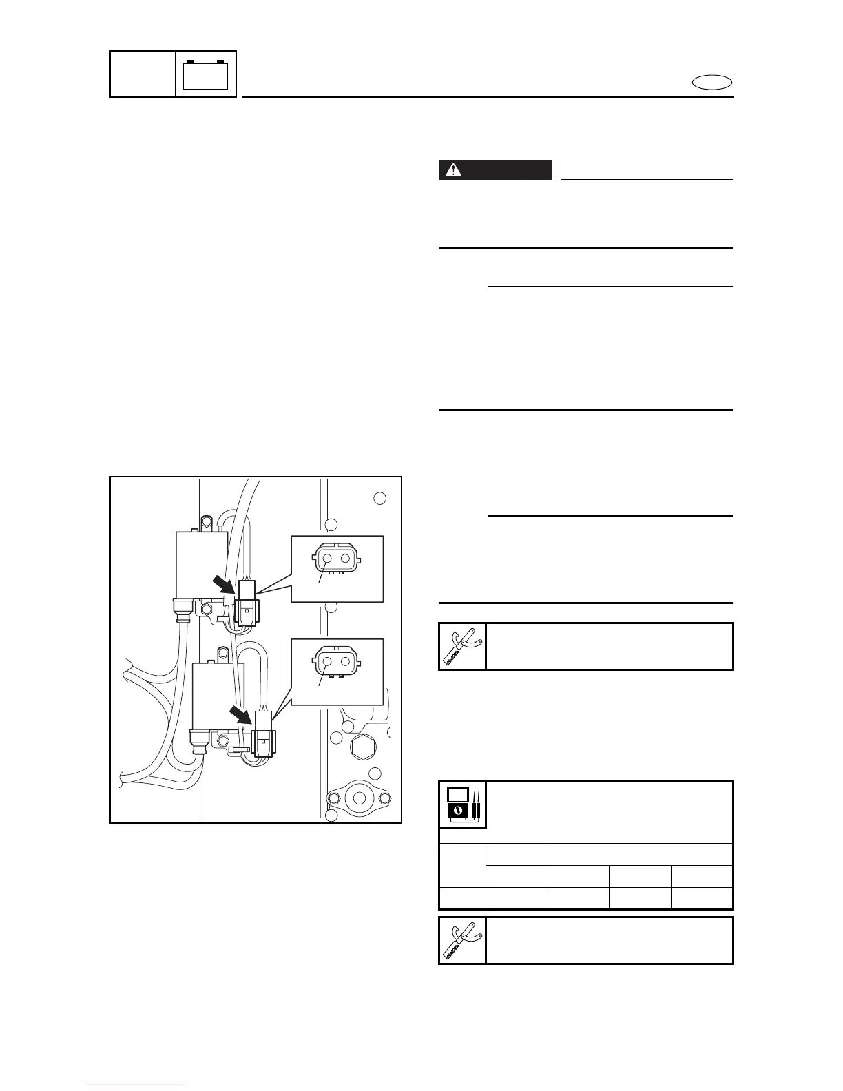
ECM unit output peak voltage
Black/red (B/R) – Ground
Black/white (B/W) – Ground
r/min
Circuit Loaded
Cranking 1,500 3,500
V 5.0 122 242 245
Test harness (2-pin)
90890-06792
B/R
B/W
8190
 Loading...