5-21
POWR
E
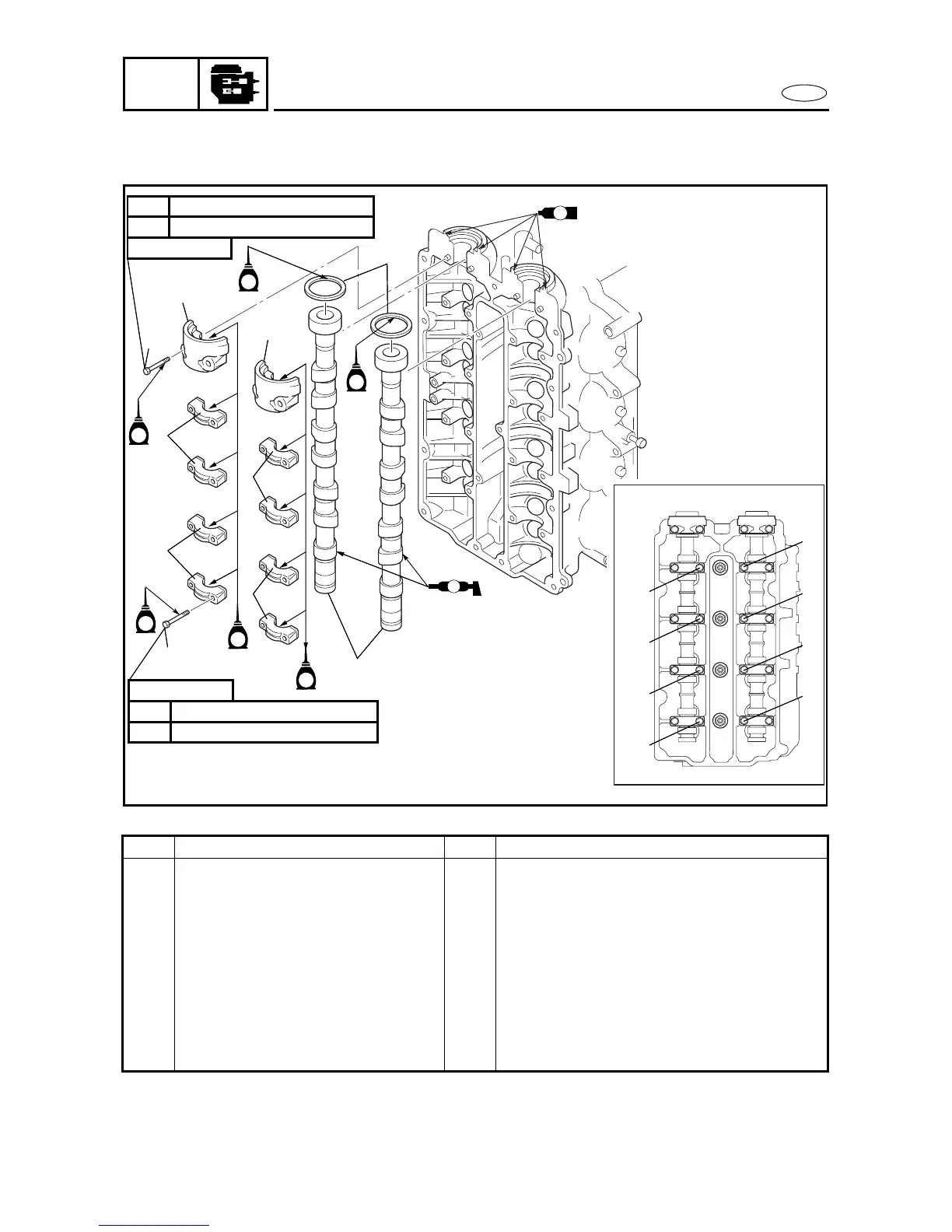
CAMSHAFTS 5
REMOVING/INSTALLING THE CAMSHAFTS 4
Order Job/Part Q’ty Remarks
Cylinder head cover Refer to “CYLINDER HEAD COVER” on
page 5-20.
1 Bolt 16
2 Bolt 4
3 Camshaft cap 2
4 Camshaft cap 8
5 Oil seal 2
6 Camshaft 2
For installation, reverse the removal
procedure.
Å
8 Nm (0.8 m • kgf, 5.8 ft • Ib)1st
17 Nm (1.7 m • kgf, 12 ft • Ib)2nd
2
4
1
6
3
3
5
M
E
E
E
E
7 × 37 mm
8 Nm (0.8 m • kgf, 5.8 ft • Ib)1st
17 Nm (1.7 m • kgf, 12 ft • Ib)2nd
7 × 48 mm
4
4
E
E
4
7
5
6
8
2
1
3
4
3
4
6
5
2
1
7
8
0
99
0
5230
CAMSHAFTS