–19–
EAA00109
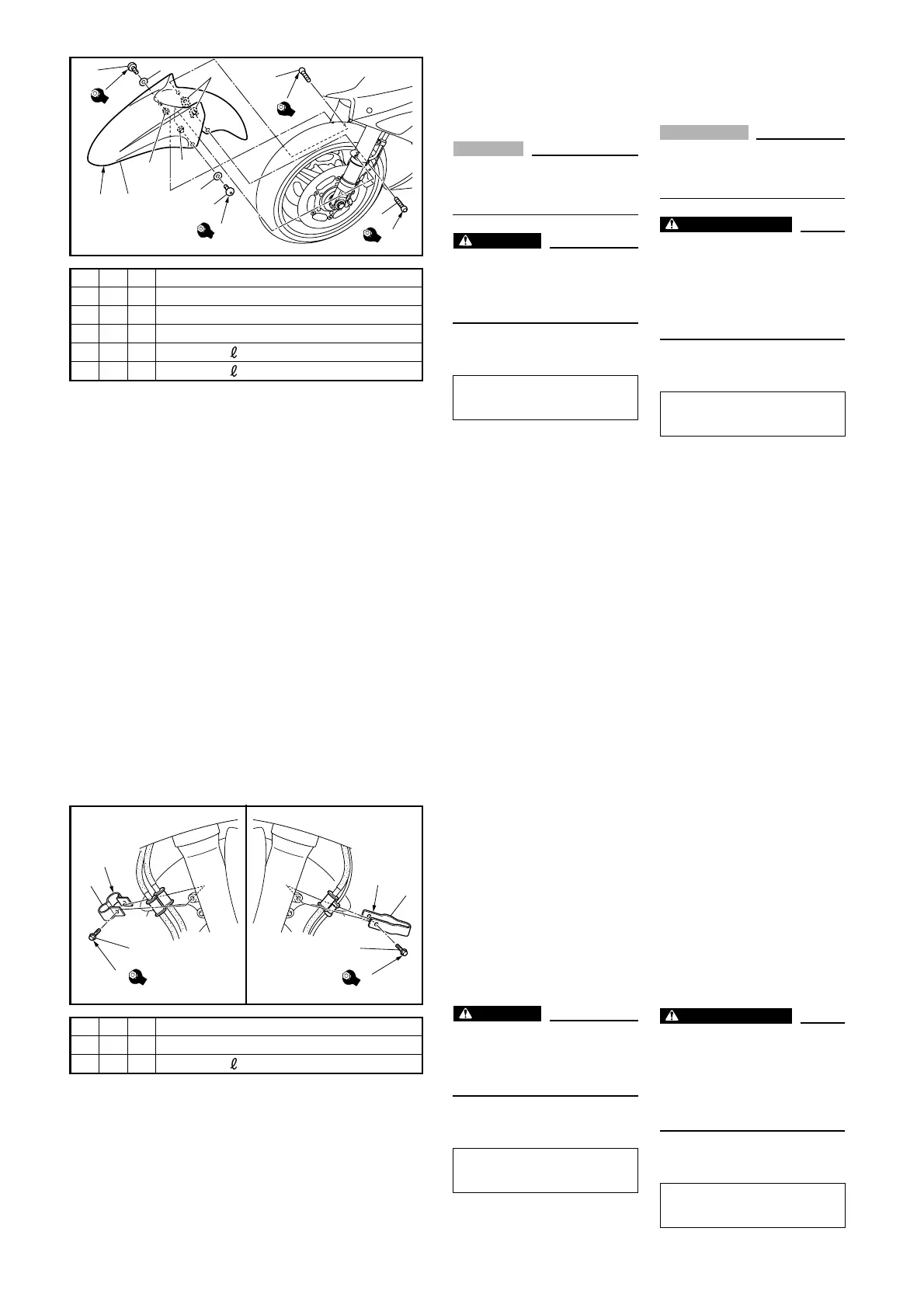
4. FRONT FENDER
A: Make sure that the front end of
the fender is installed as low
as possible.
CAUTION:
_
Be careful not to scratch the
front fender with the front fork
outer tube.
WARNING
Proper cable routing is essen-
tial to assure safe vehicle oper-
ation.
Refer to “CABLE ROUTING”.
B: Tighten the hexagon socket
bolts to specification.
Hexagon socket bolt
6 Nm (0.6 m · kg, 4.3 ft · lb)
EAA00029
5. FRONT BRAKE HOSE
HOLDERS
A: Install the brake hose holder
on the right side brake hoses.
B: Install the brake hose holder
on the left side brake hose
and front wheel sensor lead.
C: Pass the brake hose through
the brake hose holder and
secure the holder to the front
fork.
WARNING
Proper hose routing is essen-
tial to assure safe vehicle oper-
ation.
Refer to “CABLE ROUTING”.
D: Tighten the flange bolts to
specification.
Flange bolt
7 Nm (0.7 m · kg, 5.1 ft · lb)
FAA00109
4. GARDE-BOUE AVANT
A: Veiller à monter la partie avant du
garde-boue le plus bas possible.
ATTENTION:
_
Bien veiller à ne pas griffer le
garde-boue avec les fourreaux de
fourche.
AVERTISSEMENT
Un cheminement correct des
câbles est indispensable au fonc-
tionnement en toute sécurité du
véhicule.
Se reporter à “CHEMINEMENT
DES CÂBLES”.
B: Serrer les vis à tête hexagonale à
pans creux au couple spécifié.
Vis à tête hexagonale à pans creux
6 Nm (0,6 m · kg, 4,3 ft · lb)
FAA00029
5. PATTES DE BRIDAGE
DE DURITE DE FREIN
AVANT
A: Monter la patte de bridage sur les
durites de frein droites.
B: Monter la patte de bridage sur la
durite de frein gauche et sur le fil
de capteur de roue avant.
C: Faire passer la durite de frein par
la patte de bridage, puis attacher
la patte de bridage à la fourche.
AVERTISSEMENT
Un cheminement correct des duri-
tes est indispensable au fonction-
nement en toute sécurité du
véhicule.
Se reporter à “CHEMINEMENT
DES CÂBLES”.
D: Serrer les vis à collerette au cou-
ple spécifié.
Vis à collerette
7 Nm (0,7 m · kg, 5,1 ft · lb)
1C1
2 2 d = 7.3 (0.29), D = 15 (0.59)
3 V 2 d = 6 (0.24)
4 V 2 d = 6.1 (0.24), D = 18 (0.71)
5 V 2 d = 6 (0.24), = 16 (0.63)
6 V 2 d = 6 (0.24), = 20 (0.79)
6
B
6
B
6
B
6
B
2
2
3
1
5
A
4
6
4
5
6
*
1V1
2V1
3 V 2 d = 6 (0.24), = 20 (0.79)
7
D
7
D
2
3
3
1
A,D
B,C