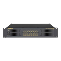
3. Over Load Protection
Perform the following test on each channel.
Input the 1 kHz, sine wave to INPUT connectors, and adjust the input signal level so that the output level is +22.2 dBu (= 25 W,
4 Ω).
Short-circuit between “+” and “–” of SPEAKERS connectors and confirm that output stops and the PROTECT indicator
lights red.
4. SIGNAL Indicator
Perform the following test on each channel with 8 Ω loaded.
Input the 1 kHz, sine wave to INPUT connectors, and adjust the input signal level so that the output level is +8.3 dBu.
Confirm that the SIGNAL indicator lights green.
5. CLIP Indicator
Perform the following test on each channel with 8 Ω loaded.
Input the 1 kHz, +7 dBu sine wave to INPUT connectors.
Confirm that the CLIP indicator lights red and the SIGNAL indicator lights green.
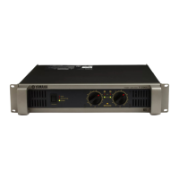
IPA8200
44