IPA8200
■ CONTENTS
(目次)
IC & DIODE FIGURES
(外形図)
..................................................................... 2
WIRING DIAGRAM
(基板結線図)
..................................................................3
BLOCK DIAGRAM
(ブロックダイアグラム)
..................................................4
CIRCUIT DIAGRAM
(回路図)
REAR 1/3 ...................................................................................................... 5
REAR 2/3 ...................................................................................................... 6
REAR 3/3 ...................................................................................................... 7
FRONT 1/4 ....................................................................................................8
FRONT 2/4 ....................................................................................................9
FRONT 3/4 .................................................................................................. 10
FRONT 4/4 .................................................................................................. 11
MOTHER A-D 1/2 ....................................................................................... 12
MOTHER A-D 2/2 ....................................................................................... 13
MOTHER E-H 1/2 ........................................................................................ 14
MOTHER E-H 2/2 ........................................................................................ 15
AMP ............................................................................................................16
INPUT POWER ........................................................................................... 17
POWER ....................................................................................................... 18
CONNECTOR, LED ..................................................................................... 19
CIRCUIT DIAGRAM
POWER AMPLIFIER
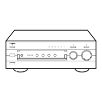
Notation for Circuit Diagrams
(回路図表記上の注意)
How to identify inter-sheet connectors
(シート間コネクタの読み方について)
Signal name
(信号名)
This indicates the location of the counter inter-sheet connector.
(The alphabet indicates horizontal direction and the number indicates
vertical direction)
対応するシート間のコネクタのあるロケーションを示します。
(アルファベットが水平方向、数字が垂直方向)
The 3-digit number indicates the destination page.
(3 桁の数字は信号の行先ページを示します。)
■ WARNING
(注意)
Components having special characteristics are marked and must be replaced with parts
having specification equal to those originally installed.
印の商品は、安全を維持するために重要な部品です。交換する場合は、安全のために必ず指定の部
品をご使用ください。