Do you have a question about the Yamaha IPA8200 and is the answer not in the manual?
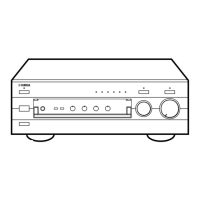
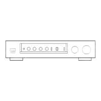
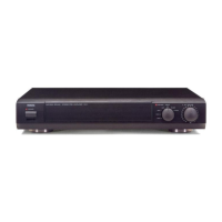
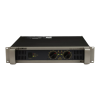
Identifies front panel switches, indicators, attenuators, and mute buttons.
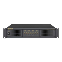
Details rear panel input/output connectors, mode/gain switches, and AC inlet.
Covers precautions for high voltage components and safe discharge procedures.
Procedure to remove the top cover and L-shaped side angles.
Remove screw and then the AMP circuit board for channel A.
Remove AMP circuit boards for channels B through H following the same procedure.
Remove screws, clip, spacer, and then the POWER circuit board (A-B).
Remove screws and spacer, then the POWER circuit board (C-D).
Remove POWER circuit boards for E-F and G-H following the same procedure.
Remove the screw and insulation sheet F.
Remove screw and bracket clip to detach MOTHER A-D board.
Remove the screw and insulation sheet E.
Remove screws and bracket clips to detach MOTHER E-H board.
Remove the screw and insulation sheet F.
Remove the screw and insulation sheet E.
Remove the two screws marked [43].
Disconnect all connector assemblies to remove the INPUT POWER circuit board.
Remove the eight [25] screws and four [24] screws.
Disconnect connectors and remove the REAR circuit board with spacers.
Remove the two screws marked [13].
Specifies voltage, temperature, humidity, load, and input signal conditions for tests.
Tests the overload protection circuit's response and indicator.
Lists performance specifications including output power, S/N ratio, THD, and frequency response.
Procedure for adjusting amplifier circuit board trimmer potentiometer for DC voltage.
| Channels | 2 |
|---|---|
| Type | Power Amplifier |
| Power Output (8 ohms) | 200W per channel |
| Power Output (4 ohms) | 300W per channel |
| Frequency Response | 20 Hz - 20 kHz |
| Input Impedance | 20k ohms |
| Signal-to-Noise Ratio | 110dB |
| Connectors | XLR |
| Dimensions | 390mm |