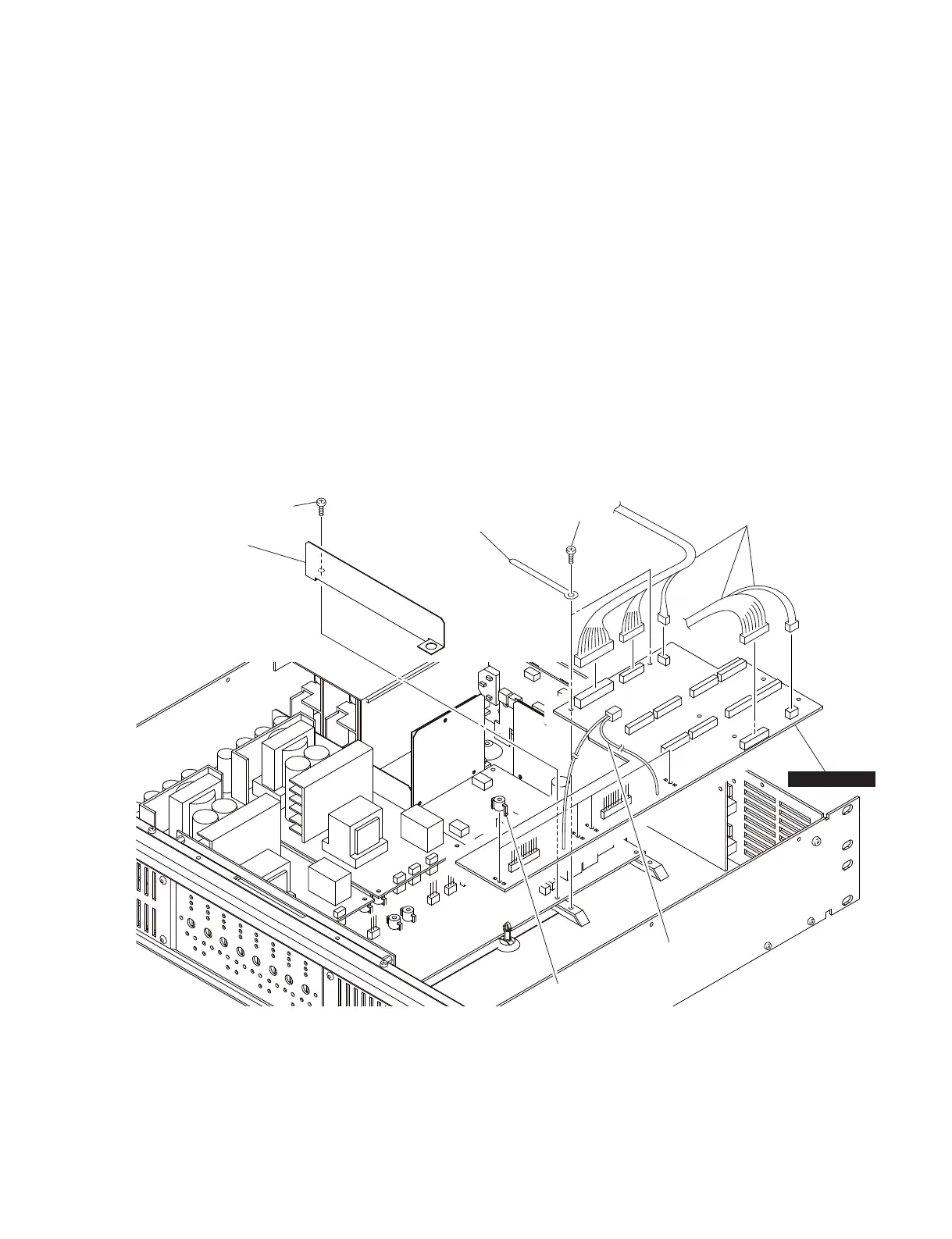
Bracket clip
ブラケットクリップ
PWB spacers
基板スペーサー
Insulation sheet E
絶縁シートE
[62C]
[72B]
MOTHER E–H
Connector assembly
束線
Connector assembly
束線
5. MOTHERE-H シート
(所要時間:約 8 分)
5-1. トップカバーを外します。(1 項参照)
5-2. AMP シート(チャンネル E、F、G、H)を外します。
(2 項参照)
5-3. POWER シート(チャンネル E-F、G-H)を外します。
(3 項参照)
5-4. [72B]のネジ、絶縁シート E を外します。(図 5)
5-5. [62C]のネジ 2 本、ブラケットクリップ 2 個を外し、
MOTHERE-H シートを外します。(図 5)
注意:基板スペーサー 4 個は、MOTHERE-H シートの構成
部品ではありません。MOTHERE-H シートを交換す
る際には、基板スペーサー 4 個を古いシートから外
して。新しいシートに取り付けてください。
5. MOTHER E-H circuit board
(Time required: about 8 minutes)
5-1. Remove the top cover. (See procedure 1.)
5-2. Remove the AMP circuit boards (channel E, F, G, H).
(See procedure 2.)
5-3. Remove the POWER circuit boards (channel E-F,
G-H). (See procedure 3.)
5-4. Remove the screw marked [72B] and the insulation
sheet E. (Fig. 5)
5-5. Remove the two (2) screws marked [62C] and the two
(2) bracket clips. The MOTHER E-H circuit board can
then be removed. (Fig. 5)
Note: The four (4) PWB spacers are not component
parts of the MOTHER E-H circuit board. When
replacing the MOTHER E-H circuit board, remove
them from old circuit board and install them to
new circuit board.
Fig. 5
(図 5)
[62C]: BIND HEAD TAPPING SCREW-B 3x8 MFZN2BL (WS522000)
B タイト+ BIND
[72B]: BIND HEAD TAPPING SCREW-B 3x8 MFZN2BL (WS522000)
B タイト+ BIND
IPA8200
15