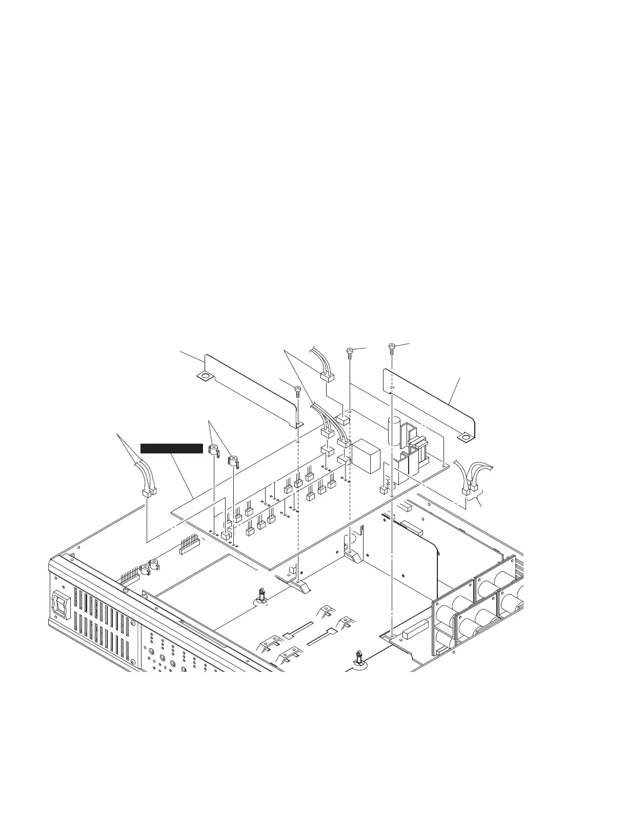
PWB spacers
基板スペーサー
Insulation sheet F
絶縁シートF
Insulation sheet E
絶縁シートE
[72B]
[43]
[72A]
INPUT POWER
Connector assembly
束線
Connector assembly
束線
Connector assembly
束線
6. INPUT POWER Circuit Board
(Time required: about 9 minutes)
6-1. Remove the top cover. (See procedure 1.)
6-2. Remove all the POWER circuit boards.
(See procedure 3.)
6-3. Remove the screw marked [72A] and the insulation
sheet F. (Fig. 6)
6-4. Remove the screw marked [72B] and the insulation
sheet E. (Fig. 6)
6-5. Remove the two (2) screws marked [43]. (Fig. 6)
6-6. Disconnect all the connector assemblies from the
INPUT POWER circuit board. The INPUT POWER
circuit board can then be removed. (Fig. 6)
Note: The eight (8) PWB spacers are not component
parts of the INPUT POWER circuit board. When
replacing the INPUT POWER circuit board, remove
them from old circuit board and install them to
new circuit board.
6. INPUTPOWER シート
(所要時間:約 9 分)
6-1. トップカバーを外します。(1 項参照)
6-2. すべての POWER シートを外します。(3 項参照)
6-3. [72A]のネジ、絶縁シート F を外します。(図 6)
6-4. [72B]のネジ、絶縁シート E を外します。(図 6)
6-5. [43]のネジ 2 本を外します。(図 6)
6-6. INPUTPOWER シートからすべての束線を外し、
INPUTPOWER シートを外します。(図 6)
注意:8 個の基板スペーサーは、INPUTPOWER シートの
構成部品ではありません。INPUTPOWER シートを
交換する際には、古いシートから基板スペーサーを
取り外して新しいシートへ取り付けてください。
[43]: BIND HEAD TAPPING SCREW-B 3x8 MFZN2BL (WS522000)
B タイト+ BIND
[72A]: BIND HEAD TAPPING SCREW-B 3x8 MFZN2BL (WS522000)
B タイト+ BIND
[72B]: BIND HEAD TAPPING SCREW-B 3x8 MFZN2BL (WS522000)
B タイト+ BIND
Fig. 6
(図 6)
IPA8200
16