7. REAR シート
(所要時間:約 5 分)
7-1. トップカバーを外します。(1 項参照)
7-2. [25]のネジ8本、[24]のネジ 4 本を外します。(図 7)
7-3. REAR シートからすべての束線を外し、REAR シー
トを六角スペーサー 4 本、ネジ 4 本と共に外します。
(図 7)
注意:六角スペーサー 4 本、ネジ 4 本は、REAR シートの
構成部品ではありません。REAR シートを交換する
際には、古いシートから六角スペーサー 4 本、ネジ 4
本を外して、新しいシートに取り付けてください。
7. REAR Circuit Board
(Time required: about 5 minutes)
7-1. Remove the top cover. (See procedure 1.)
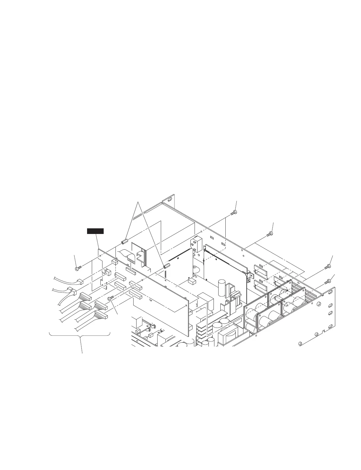
7-2. Remove the eight (8) screws marked [25] and the four
(4) screws marked [24]. (Fig. 7)
7-3. Disconnect all the connector assemblies from the
REAR circuit board. The REAR circuit board can
then be removed together with the four (4) hexagonal
spacers and four (4) screws. (Fig. 7)
Note: The four (4) hexagonal spacers and four (4)
screws are not component parts of the REAR
circuit board. When replacing the REAR circuit
board, remove them from old circuit board and
install them to new circuit board.
[24]: BIND HEAD SCREW 3x6 MFZN2B3 (WS522500)
小ネジ+ BIND
[25]: PAN HEAD SCREW M2.6x6 NI-BL (WS522400)
小ネジ+ PAN
Fig. 7
(図 7)
Hexagonal spacers
六角スペーサー
Screws
ネジ
Screws
ネジ
[25]
[25]
[24]
[24]
REAR
Connector assemblies
束線
IPA8200
17