+
OLP/STANDBY
0.82V
OLP/STANDBY
+
OVERVOLTAGE
5.25V
OVP
Input Brown-Out Protection
(IBOP)
+
+
VIN
ENABLE_th
1.5V
SQ
QR
VIN
BROWNOUT_th
0.82V
5V
20k
IBOP
+
V
PCL
1.08V
Soft Over Current (SOC)
V
SOC
0.73V
Peak Current Limit (PCL)
SOC
40k 40k
+
PCL
-1x
300ns
Leading Edge
Blanking
UVLO
+
+
VCC
ON
10.5V
SQ
QR
VCC
OFF
9.5V
UVLO
R
SENSE
C
OUT
L
BST
R
ISENSE
+–
Bridge
Rectifier
C
ISENSE
LINE
INPUT
D
BST
V
OUT
C
VCOMP-P
R
VCOMP
C
VCOMP
+
gmv
Voltage Error
Amplifier
+
gmi
C
ICOMP
SQ
QR
PWM
Comparator
K
PC
(s)
SOC
M
2
M
1
EMI Filter
ICOMP
VCOMP
C
IN
5V
65kHz
Oscillator
R
LOAD
FAULT
C
VCC
Auxilary
Supply
Current
Amplifier
3
ISENSE
2
ICOMP
VINS
4
5
VCOMP
6
VSENSE
7
1
VCC
GND
8
GATE
GAIN
M
1
EDR
+
UNDERVOLTAGE
4.75V
EDR
C
VINS
R
VINS1
R
VINS2
VCC
Gate Driver
UVLO
IBOP
OLP
SQ
QR
PCL
OVP
Clock
Pre-Driveand
Clamp Circuit
R
FB1
R
FB2
Q
BST
10k
R
GATE
C
VSENSE
+
FAULT
PWM
RAMP
M
2
Min Off Time
+
SS
EDR
Fault
Logic
Fault
100μA
GND
ICOMP
ISENSE
GATE
VCC
VSENSE
VCOMP
VINS
1
2
3
4
8
7
6
5
1
2
3
4-V
8
7
6
5
Output A +V
Non-Inverting
Input A
-DC Voltage Supply
+DC Voltage
Supply
Output B
Inverting
Input B
Non-Inverting
Input B
Inverting
Input A
+-
+-
12
14
8
13
11
9
10
6
1
2
16
15
3
4
5
+
-
V
CC
C1
C1
Output Control
Output Control
C2
E1
E2
C2
E1
E2
RT
CT
Dead-Time
Control
Ref Out
GND
VCC
RT
CT
Ref Out
GND
Non-Inv. Input
Non-Inv. Input
Inv. Input
Inv. Input
Feed-Back
Dead-Time
Control
Non-Inv. Input
Inv. Input
Non-Inv. Input
Inv. Input
Feed-Back
7
+
-
+
-
+
-
Reference
Regulator
Low Voltage
Stop
Oscillator
EA
EA
Dead Time
Comparator
PWM
Comparator
T /
F
F
1
2
3
4
5
6
7
8
9
10
16
15
14
13
12
11
S
R
Q
Q
S
R
Q
Q
Max Duty
Clock
Sawtooth
1
Drain
Control
3
2
Source
Gate driver
Power
MOSFET
Blanking pulse
generation
circuit in on-state
Drain current
for detection
Overcurrent
protection
Restart
trigger
Overheat
protection
Start-up constant current
Timer intermittent
operation circuit
Internal power supply
For control over
light load detecting
intermittent oscillation
Oscillator
V-I converter
Slope
compensation
Air lamp
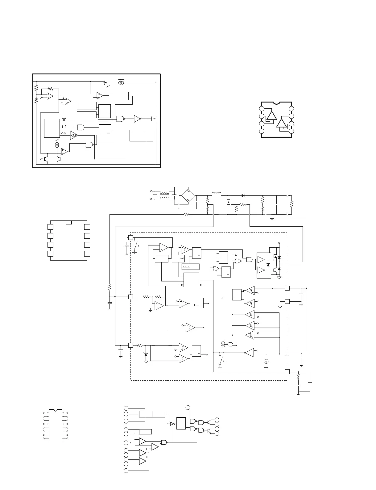
rUCC28019DR (YA885A0)
PFC Controller
POWER: IC901
rMIP2E4DMY (YA883A0)
IPD
INPUT POWER: IC971
r61$(45"5 (X8569A0)
SWR Controller
POWER: IC902
r/+..%5& (AAX6275)
Operational Amplifier
REAR: IC11, 31, 51, 71
FRONT: IC101, 102, 202, 301, 302, 402,
IC501, 502, 602, 701, 702, 802
MOTHER A-D: IC1101, 1301
MOTHER E-H: IC1501, 1701
■
IC BLOCK DIAGRAM
(IC ブロック図)
IPA8200
22