Bracket clip
ブラケットクリップ
[76A]
[76B]
[76B]
[76A]
[76C]
[76C]
[76D]
[76D]
(CH A–B)
POWER
(CH C–D)
POWER
(CH G–H)
POWER
(CH E–F)
POWER
Spacers
スペーサー
Spacers
スペーサー
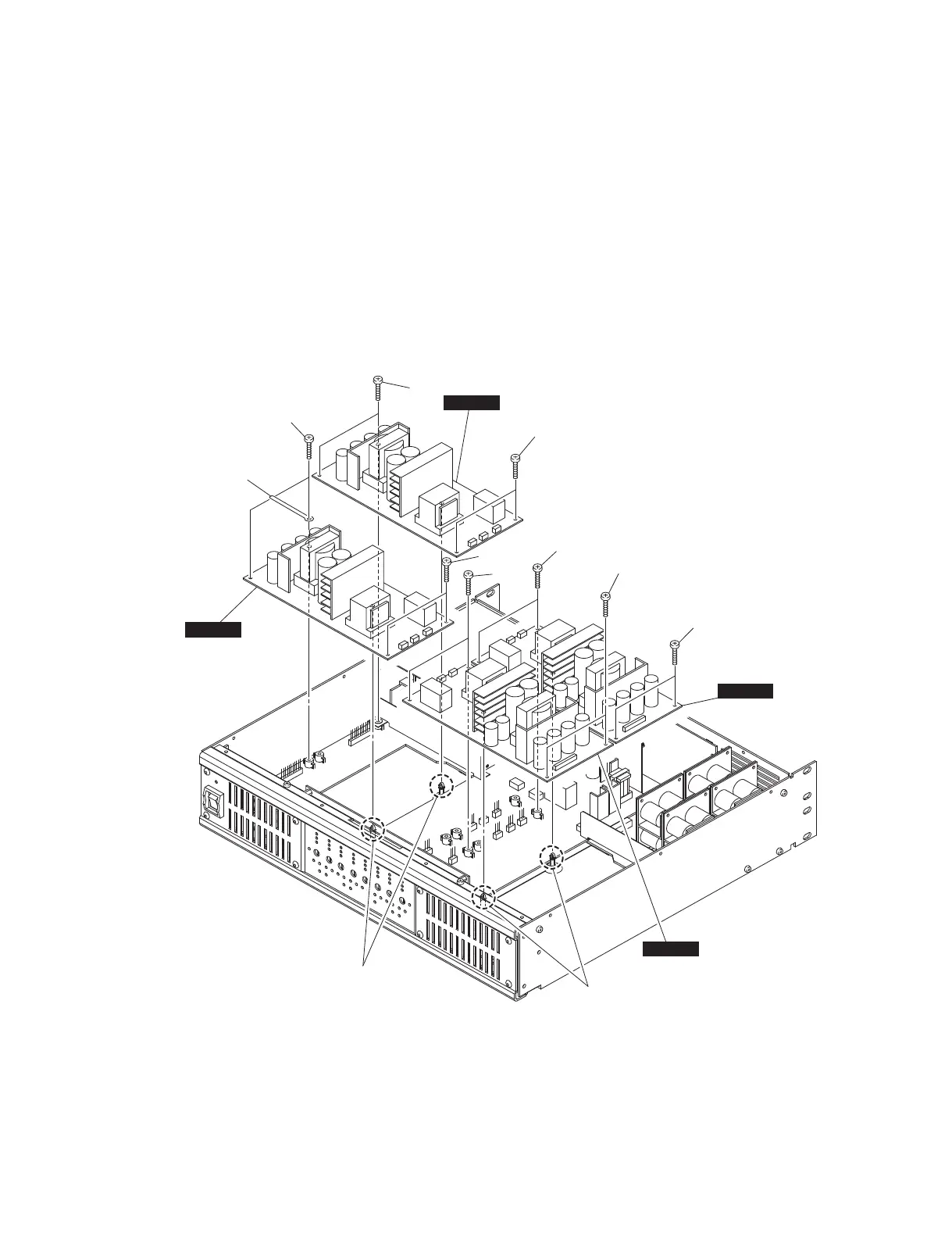
3. POWER シート
(所要時間:約 6 分)
3-1. トップカバーを外します。(1 項参照)
3-2. [76A]のネジ 4 本、ブラケットクリップを外します。
スペーサーを解除し、POWER シート(チャンネル
A-B)を外します。(図 3)
3-3. [76B]のネジ 4 本を外します。スペーサーを解除し、
POWER シート(チャンネル C-D)を外します。(図 3)
3-4. 同様の方法で、POWER シート(チャンネル E-F、
G-H)を外します。(図 3)
3. POWER Circuit Boards
(Time required: about 6 minutes)
3-1. Remove the top cover. (See procedure 1.)
3-2. Remove the four (4) screws marked [76A] and the
bracket clip. Release the spacer. The POWER circuit
board (channel A-B) can then be removed. (Fig. 3)
3-3. Remove the four (4) screws marked [76B]. Release
the spacer. The POWER circuit board (channel C-D)
can then be removed. (Fig. 3)
3-4. In the same manner, the POWER circuit boards
(channel E-F, G-H) can then be removed. (Fig. 3)
[76A]: BIND HEAD TAPPING SCREW-B 3.0x16 NI-BL (WT892700)
B タイト+ BIND
[76B]: BIND HEAD TAPPING SCREW-B 3.0x16 NI-BL (WT892700)
B タイト+ BIND
[76C]: BIND HEAD TAPPING SCREW-B 3.0x16 NI-BL (WT892700)
B タイト+ BIND
[76D]: BIND HEAD TAPPING SCREW-B 3.0x16 NI-BL (WT892700)
B タイト+ BIND
Fig. 3
(図 3)
IPA8200
13