28
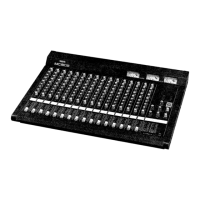
MW10
*1 Measure with 2TR IN/USB level control set at the MAX position.
*2 Set 2TR IN/USB switch ON (TO C-R) when you measure C-R OUT and PHONES OUT.
3.4 USB
3.4-1 Recording
Record to the personal computer by way of USB in the state in Table 3.4-1. (Refer to 3.1 for other settings.)
3.4-2 Gain
The output levels shall be within the range specified in the Table 3.4-2 when you play back the recorded file by
way of USB.
* Set the [2TR IN/USB] switch to off (TO ST) during playback.
*1 Measure with the 2TR IN/USB level control set at the MAX position.
*2 Don’t input the signal to all other input terminals.
*3 Set the volume control of WINDOWS in MAX.
INPUT INPUT Level ST L OUT ST R OUT C-R OUT L
*2
C-R OUT R
*2
PHONES L
*2
PHONES R
*2
L -35.8 -12 +/-2 -- -2 +/-2 -- -13.5 +/-2 --
R -- -12 +/-2 -- -2 +/-2 -- -13.5 +/-2
Table 3.3-6 Input Terminal 2TR IN L,R [dBu]
!1
!2
INPUT INPUT Level CH1 PAN control
L CH INSERT IN 1 -16 L (turned counterclockwise fully)
R R (turned clockwise fully)
Table 3.4-1 [dBu]
ST L OUT ST R OUT
L +12 +/-3 --
R -- +12 +/-3
Table 3.4-2 [dBu]
3.5 Frequency Characteristics
In the signal routes of the Table 3.3-1 to 3.3-6 indicated with q to !2, the 20Hz and 20kHz frequency response of
each output shall be within the range of 0dB +1/-2.5dB compared to the 1kHz (0dB).
* The 20Hz level when the GAIN volume is Max shall be within the range of 0dB +1.0/-4.5 dB compared to
the 1kHz (0dB).
* In the route q, check every OUT when the signal is fed to CH1, and check only the ST L OUT when the signal
is fed to CH2 and other channels.
*In the route r, check only the ST L OUT and the ST R OUT.
3.6 HPF
In the state of the Table 3.3-1 and 3.3-2, feeding 80 Hz -36dBu signal, and setting the GAIN to MIN, the STEREO
L OUT level obtained when the switch is set to ON shall be within the range of -3 dB +2/-2dB compared to
the level obtained when the switch is set to OFF.
INPUT INPUT Level ST L OUT ST R OUT
L/MONO -8 +4 +/-2 +4 +/-2
R -- +4 +/-2
Table 3.3-5 Input Terminal RETURN L,R [dBu]
o
!0
 Loading...