30
MW10
3.12 Maximum Output
In the state 3.1, the distortion factor shall be less than 1% when the output level is +20dBu at ST L OUT, ST R
OUT, AUX1 OUT, AUX2 OUT and C-R OUT.
The distortion factor shall be less than 1% when the output level is +7.5dBu at PHONES (L/R).
In measuring the ST L OUT, the ST R OUT, set the PAN or PAN/BAL or BAL Control to L or R fully respectively.
In measuring the C-R OUT and PHONES, set the C-R/PHONE Control to MAX.
3.13 Equivalent Input Noise
In the state 3.1, connect between the CH INPUT MIC terminals (2pin-Hot and 3pin-Cold) with 150 ohms, the noise
level obtained at ST L OUT shall be less than -51.5dBu.
If it is over than -51.5dBu, calculate the input converted noise level (= noise level - channel gain) and it shall be
less than -127.5dBu.
Connect between the ST INPUT MIC terminals (2pin-Hot and 3pin-Cold) with 150 ohms, the noise level obtained
at ST L OUT shall be less than -47.5dBu.
If it is over than -47.5dBu, calculate the input converted noise level (= noise level - channel gain) and it shall be
less than -123.5dBu.
(Minimize the LEVEL VR other than the measurement channel. Noise is measured with a 12.7kHz -6dB/octave low
pass filter.)
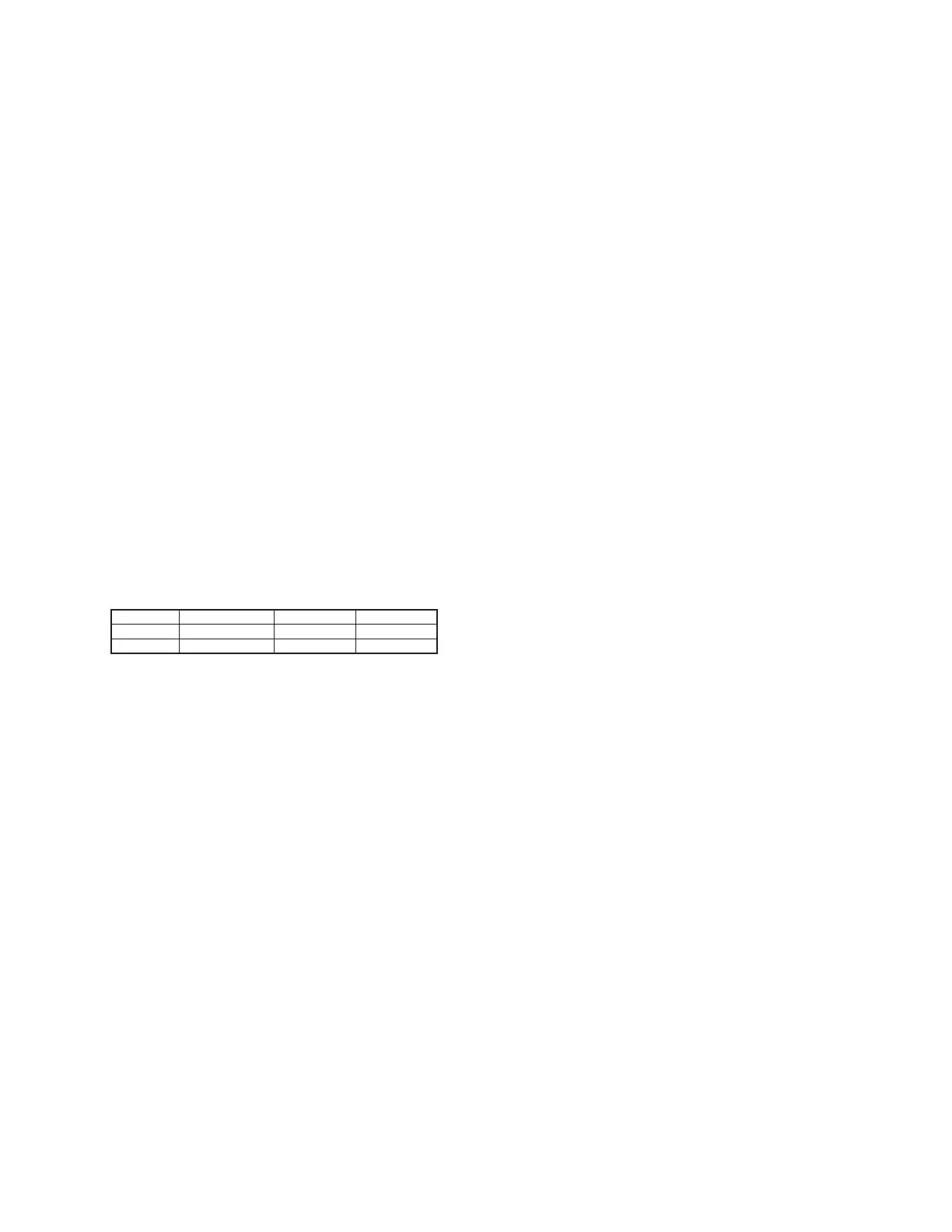
3.14 Residual Noise
In the state 3.1, set the Level Control of all input CH to MIN.
Then when the MASTER VR set to the MAX or MIN position, the noise level shall be less than the level specified
in the Table 3.14-1.
* When measuring the AUX OUT, set the all CH AUX Level control to CENTER.
* When measuring the C-R OUT and the PHONES, set the ST VR to MIN.
(Noise is measured with a 12.7kHz -6dB/octave low pass filter.)
3.15 PHANTOM
Connect a 10kΩ (1W or more) load resistance between the pin 1 and 2 of the MIC and short-circuit between the
pin 2 and 3.
Turn on the PHANTOM switch (LED shall light) and the voltage between pin 1 and 2 shall be within +35 +/-3V.
3.16 Preparation of delivery
Factory set
• EQ Gain control : CENTER
• PAN, PAN/BAL, BAL control : CENTER
• CH AUX control : CENTER
• Other VR control : MIN
• Lock-PUSH switch : OFF
• ON/STANDBY switch : STANDBY
VR STEREO OUT AUX OUT C-R OUT
MAX -81.0 -85.0 -79.0
MIN -100.0 -- -88.0
Table 3.14-1 [dBu]
 Loading...